
 WhatsApp: +86 16626708626
 Email:
  Phone: +86 16626708626
Description
3. Key Technical Specifications
| Parameter | Value |
|---|---|
| Manufacturer | GE Fanuc / Emerson |
| Model | IC697PWR711K |
| Product Series | Series 90-70 |
| Product Type | 100 W Power Supply Module |
| Input Voltage (AC) | 90–264 VAC, 47–63 Hz |
| Input Voltage (DC) | 100–150 VDC |
| Rated Input | 120/240 VAC or 125 VDC |
| Maximum Output Power | 100 W |
| Output Voltages | +5 VDC, +12 VDC, -12 VDC |
| +5 VDC Output | 4.90–5.25 VDC (5.07 V nominal) |
| Hold-Up Time | Minimum 21 ms |
| Power Factor | >0.93 |
| Installation Position | Leftmost slot of the Series 90-70 rack |
| Operating Temperature | 0 °C to +60 °C |
| Storage Temperature | -40 °C to +85 °C |
The IC697PWR711K supplies regulated power to CPUs, I/O modules, and communication modules in the Series 90-70 PLC platform. It accepts either AC or DC input and provides a combined output capacity of 100 W.
4. Product Introduction
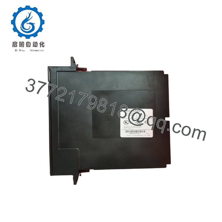
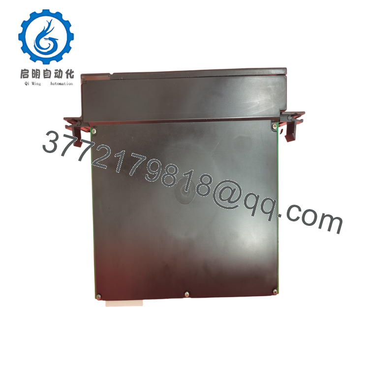
The GE IC697PWR711K is a 100 W power supply module designed for the Series 90-70 PLC platform. It converts either 120/240 VAC or 125 VDC input into the regulated backplane voltages required by CPUs, communication modules, and I/O modules. The power supply installs in the dedicated left-side power supply slot and distributes power throughout the PLC rack.
Revision K belongs to the mature hardware revisions of the IC697PWR711 family and remains widely deployed in existing Series 90-70 installations. Although the platform has reached legacy status, this module continues to support many critical industrial applications where system stability is more important than platform migration.

- IC697PWR711K
- IC697PWR711K
5. Installation & Configuration Guide
Stage 1 – Pre-Installation Preparation (10 Minutes)
⚠️ Safety First
- Notify operations of the scheduled shutdown.
- Bring the process to a safe operating condition.
- Apply Lockout/Tagout (LOTO).
- Disconnect incoming AC or DC power.
- Wait at least 5 minutes before servicing the rack.
Tools Required
- Grounded ESD wrist strap
- PH1 screwdriver
- Fluke 115 digital multimeter
- Wire identification labels
- Smartphone for documentation
Data Backup
Before removal:
- Photograph all incoming power wiring.
- Record input voltage.
- Record rack configuration.
- Calculate the total rack power consumption.
- Verify all installed module locations.
Stage 2 – Removing the Existing Module (5 Minutes)
- Verify incoming power is completely isolated.
- Disconnect all input power wiring.
- Remove the retaining hardware.
- Slide the power supply straight out.
- Inspect:
- Backplane connector
- Power terminals
- Fan openings
- Signs of overheating
- Connector discoloration
⚠️ Do not discard the original module until the replacement has completed a full operational test.
Stage 3 – Installing the New Module (10 Minutes)
- Wear a grounded ESD wrist strap.
- Verify the replacement model:
IC697PWR711K
- Install the module into the dedicated power supply slot.
- Ensure the connector is fully seated.
- Tighten mounting hardware.
- Reconnect incoming AC or DC wiring.
- Verify protective earth continuity.
Installation Checklist
- Correct catalog number
- Input voltage verified
- Protective earth connected
- Backplane connector seated
- Wiring polarity confirmed
Stage 4 – Power-On & Functional Testing (15 Minutes)
Pre-Power Checks
- Verify no short circuit on incoming power.
- Measure protective earth continuity.
- Confirm correct input voltage selection.
- Inspect terminal tightness.
Startup Procedure
- Apply input power.
- Observe CPU startup.
- Verify rack LEDs.
- Measure:
- +5 VDC
- +12 VDC
- -12 VDC
- Confirm all installed modules initialize correctly.
- Perform a complete PLC functional test.
⚠️ Troubleshooting
If the rack fails to power correctly:
- Verify input voltage is within specification.
- Inspect the backplane connector.
- Check total rack power loading.
- Verify the internal fuse if applicable.
- Confirm no downstream module is creating an overload.
SOP Quality Verification
Every production-critical IC697PWR711K should undergo documented verification before shipment.
1. Inbound Inspection & Traceability
- Verify OEM labels and serial numbers.
- Inspect for corrosion, scratches, UV discoloration, and rework.
- Confirm hardware revision.
- Review traceability records.
2. Live Functional Testing
Testing should be completed using a genuine Series 90-70 PLC rack.
Verification includes:
- Power-on self-test
- Output voltage measurement
- Full rack startup
- Backplane power verification
- Continuous operation exceeding 24 hours
- Thermal monitoring under load
- Functional test report generation
Test photographs and startup videos should be available upon request.
3. Electrical Verification
- 500 V insulation resistance test (>10 MΩ)
- Ground continuity verification
- Output voltage calibration
- Input current measurement
4. Configuration Verification
- Record hardware revision.
- Verify jumper configuration where applicable.
- Document output voltage measurements.
5. Final QC
- QC inspector approval
- Anti-static packaging
- Bubble-wrap protection
- Heavy-duty corrugated carton
- QC Passed label with inspection date
Technical Pitfalls & Survival Guide
❗ Don’t Calculate Power Only Once
One of the most common mistakes is replacing the power supply without recalculating rack loading.
I’ve seen plants add several analog and communication modules over the years while keeping the original power supply. Everything appeared stable until startup, when voltage dipped below specification because the rack was operating near its maximum capacity. Always calculate the total +5 VDC, +12 VDC, and -12 VDC load and maintain at least a 20% capacity margin.
❗ Verify Input Voltage
The IC697PWR711K accepts both AC and DC input.
Before energizing the rack, verify whether the installation uses 120/240 VAC or 125 VDC. I’ve seen unnecessary troubleshooting simply because a replacement was wired for the wrong supply source.
❗ Inspect the Backplane Connector
Power supply failures are not always caused by the module itself.
Burned or oxidized backplane contacts can create voltage drops that resemble an internal power supply fault. Inspect the connector carefully before installing the replacement.
❗ Don’t Ignore Hold-Up Time
The module provides approximately 21 ms of hold-up time during AC input loss. If your facility experiences frequent voltage sags beyond this duration, investigate the upstream power system or consider installing an industrial UPS rather than repeatedly replacing the PLC power supply.
❗ Electrostatic Discharge (ESD)
Although this is a power supply, it contains control electronics that are vulnerable to static discharge.
Always use a grounded wrist strap and handle the module only on an ESD-safe work surface.
Keep these checks in mind and you’ll avoid most of the startup problems that extend scheduled maintenance windows.
6. Frequently Asked Questions (FAQ)
Q1. What is the function of the IC697PWR711K?
The IC697PWR711K converts 120/240 VAC or 125 VDC input into regulated +5 VDC, +12 VDC, and -12 VDC outputs that power the Series 90-70 PLC backplane and installed modules.
Q2. Can I replace the IC697PWR711K while the PLC is energized?
No.
The power supply is not hot-swappable. Disconnect incoming power and follow Lockout/Tagout procedures before replacing the module.
Q3. Is the IC697PWR711K obsolete?
Yes.
The Series 90-70 platform is a legacy GE Fanuc product family. New Original inventory is limited, while New Surplus and professionally tested refurbished modules remain available for maintaining installed systems.
Q4. How much power can this module provide?
The module provides a maximum combined output of 100 W across its regulated outputs. Proper rack loading calculations should always be completed before adding additional modules.
Q5. Why does the CPU report a power fault after replacing the power supply?
Common causes include:
- Incorrect input voltage
- Overloaded rack
- Loose backplane connector
- Faulty field wiring
- Internal short circuit in another module
In practice, many “power supply failures” are actually caused by downstream hardware rather than the power supply itself.
Q6. What inspections should I request before shipment?
For production-critical applications, request:
- OEM serial number verification
- Visual inspection for corrosion and connector damage
- Output voltage verification under load
- Functional testing on a genuine Series 90-70 rack
- Continuous 24-hour burn-in
- Insulation resistance testing
- Hardware revision documentation
- ESD-safe packaging with QC records
Requesting load-test data and startup photographs before shipment can reduce commissioning risk and shorten maintenance outages for legacy Series 90-70 systems.



