
 WhatsApp: +86 16626708626
 Email:
  Phone: +86 16626708626
Description
Key Technical Specifications
- Model: IC754VSF15CTD
- Manufacturer: GE Fanuc / GE Intelligent Platforms
- Product Family: QuickPanel View
- Display Type: 15.1-inch color TFT LCD
- Display Resolution: 1,024 × 768 pixels
- Touch Technology: Resistive touchscreen, 12-bit resolution
- DRAM: 64 MB standard; expandable configurations may vary
- Flash Memory: 64 MB
- SRAM: 512 KB battery-backed memory
- Operating System: Microsoft Windows CE
- Application Runtime: Proficy View Machine Edition preloaded on applicable configurations
- Ethernet: One 10/100 Mbps Ethernet port
- Serial Communications: RS-232/RS-485 port and separate RS-232 port
- Storage: Type II CompactFlash interface
- USB: USB 1.1 compatibility
- Input Voltage: 12 to 30 VDC
- Nominal Supply: 24 VDC
- Power Consumption: Approximately 48 W; verify the nameplate and hardware revision
- Operating Temperature: 0 to 50 °C for the 15-inch configuration
- Panel Cutout: Approximately 379 × 305 mm; verify the mechanical drawing before cutting a panel
- Environmental Protection: NEMA 4/4X bezel rating on applicable configurations
- Firmware: Windows CE and QuickPanel View runtime version must match the existing application
Product Introduction
The GE Fanuc IC754VSF15CTD is a 15.1-inch QuickPanel View industrial HMI for operator display, alarm handling, trends, and machine-control functions. It uses a 1,024 × 768 color TFT display, resistive touchscreen, 24 VDC nominal power, Ethernet, and serial communications for PLC and field-device connectivity.
The terminal includes 64 MB DRAM, 64 MB Flash, and battery-backed SRAM. It is suitable for maintaining installed GE Fanuc HMI systems, but the application runtime, Windows CE image, CompactFlash contents, communication drivers, and touchscreen calibration must match the existing installation.
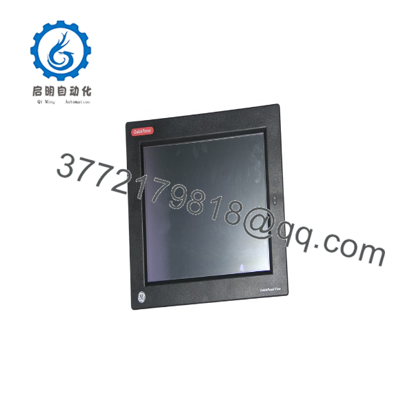
IC754VSF15CTD
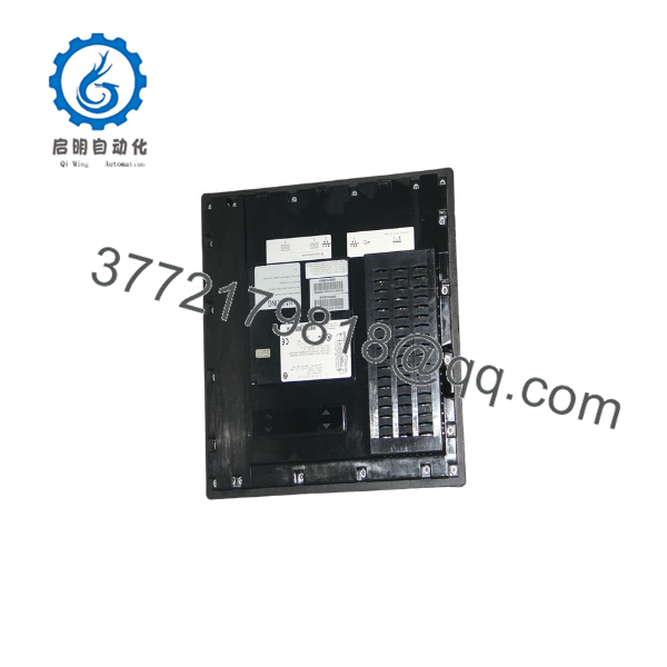
IC754VSF15CTD
Installation & Configuration Guide
Stage 1: Pre-Installation Preparation — 10 to 15 Minutes
⚠️ Safety First: Notify operations, place the machine in a verified safe state, and complete lockout/tagout on the 24 VDC circuit. Wait at least 5 minutes for stored energy to discharge, then verify the power terminals with a multimeter.
Tools Required:
- ESD wrist strap and grounded ESD mat
- PH1 screwdriver
- Multimeter
- Wire labels and marker
- Smartphone or camera for photographs
- Panel fastener tool or suitable nut driver
- Correct configuration cable or CompactFlash media
Data Backup:
- Export or copy the HMI application, screen files, alarm configuration, recipes, and user-management data.
- Record the HMI IP address, subnet mask, gateway, PLC address, serial-port settings, and communication driver.
- Photograph the rear connector layout, power wiring, Ethernet connection, serial cables, mounting clips, and nameplate.
- Record the Windows CE image, QuickPanel runtime, Proficy View Machine Edition, and application versions.
- Confirm the replacement has the same display size, bezel style, connector arrangement, and loaded or intermediate configuration.
Stage 2: Removing the Old HMI — 10 Minutes
- Stop the HMI runtime and shut down the connected control equipment according to the site procedure.
- Remove the cabinet cover or rear access protection.
- Verify that the 24 VDC supply is de-energized.
- Label and disconnect the power, Ethernet, serial, USB, and CompactFlash connections.
- Support the HMI from the front while loosening the rear mounting clips or fasteners.
- Remove the unit straight from the panel opening. Do not drag the bezel across the cutout.
- Inspect the panel gasket, mounting clips, cutout edges, and cable insulation.
- Keep the old HMI intact until the replacement has loaded the application and communicated with the PLC.
Stage 3: Installing the New HMI — 10 to 15 Minutes
- Put on the grounded ESD wrist strap and verify the replacement model is IC754VSF15CTD.
- Compare the display, bezel, rear connectors, power label, and serial number with the removed unit.
- Confirm that the existing panel cutout accepts the replacement. Do not force a 15-inch unit into a cutout intended for a different QuickPanel size.
- Transfer the CompactFlash card only after confirming that the application files are compatible and backed up.
- Insert the HMI into the panel opening with the gasket seated evenly against the enclosure.
- Install the mounting clips or fasteners in a cross pattern. Tighten evenly; excessive torque can distort the bezel or damage the touchscreen.
- Reconnect the 24 VDC wiring with correct polarity and protective-earth bonding.
- Reconnect Ethernet and serial cables according to the photographs and labels.
- Confirm that no cable applies mechanical force to the rear connectors.
Self-Checklist:
- Correct IC754VSF15CTD model verified
- [] Panel cutout and gasket verified
- [] 24 VDC polarity checked
- [] Ethernet and serial cables identified
- [] CompactFlash contents backed up
- [] Mounting clips tightened evenly
- [] Protective earth and signal-ground arrangement checked
Stage 4: Power-On and Commissioning — 10 to 20 Minutes
- Check the 24 VDC supply with the multimeter before connecting it to the HMI.
- Verify that the supply can provide the HMI load without excessive voltage drop.
- Energize the HMI with machine outputs inhibited where the process permits.
- Confirm the boot sequence and allow Windows CE and the HMI runtime to initialize.
- Verify display brightness, touchscreen response, and touch calibration.
- Configure the IP address, subnet mask, and gateway if the replacement did not retain them.
- Confirm the PLC communication driver, station address, baud rate, parity, and stop-bit settings.
- Test Ethernet or serial communication with the PLC while monitoring diagnostics.
- Open several screens, verify alarm acknowledgment, test trends, and confirm recipe or data-logging access.
- Perform a controlled operator-function test before returning the machine to production.
⚠️ Troubleshooting Note: If the HMI boots to the Windows CE desktop, the runtime or startup configuration may be missing. If the application loads but shows communication errors, check the PLC driver, IP address, serial settings, cable pinout, and CompactFlash application version before changing the control program.
Frequently Asked Questions (FAQ)
Can I hot-swap the IC754VSF15CTD?
No. Isolate the 24 VDC supply before disconnecting or installing the HMI. Removing the unit under power can damage connectors, corrupt CompactFlash data, and leave the operator interface in an unknown state.
Is the IC754VSF15CTD obsolete?
It is a legacy QuickPanel View terminal, and replacement stock is typically sourced from surplus, used, or refurbished inventories. Availability varies by configuration and bezel revision. Confirm the display, memory, firmware, runtime, and communication options rather than purchasing by the base model alone.
Is this a direct replacement for another 15-inch QuickPanel?
Only when the original unit has the same mechanical cutout, connector layout, power range, memory configuration, and application environment. Some QuickPanel View and QuickPanel Control models look similar but use different runtime software or communication hardware. Verify the full catalog number and suffix before installation.
Will I lose the HMI application when I remove the old unit?
Usually, the application resides in nonvolatile Flash or CompactFlash media, but you should not rely on that. Back up the project, recipes, alarms, user database, and communication configuration before shutdown. If the replacement includes different Flash contents or a different runtime version, the HMI may boot without opening the production application.
Does this HMI support Ethernet and serial PLC communications?
Yes. The family provides Ethernet and serial interfaces, including RS-232 and RS-485 configurations. The actual usable protocol depends on the installed runtime, driver package, cable pinout, and PLC application. Confirm the existing driver and port assignment before commissioning.
Why is the price lower than a current HMI?
This model is a legacy terminal rather than a current-generation HMI. Lower pricing commonly reflects surplus or refurbished inventory, discontinued OEM support, limited firmware availability, or the absence of a factory-sealed package. Obtain the exact condition, warranty, test report, and return terms in writing.
What testing should the supplier provide?
Request a power-on boot video, display and touchscreen test, Ethernet and serial communication test, Flash and SRAM verification, touchscreen calibration record, and confirmation of the installed runtime version. For refurbished stock, request inspection photographs, serial-number traceability, a continuous run test, QC sign-off, ESD packaging, and the warranty period. Verify precise application compatibility against the OEM manual before installation.



