
 WhatsApp: +86 16626708626
 Email:
  Phone: +86 16626708626
Description
Key Technical Specifications
| Parameter | Value |
| Number of Channels | 4 |
| Output Signal Range | 4 mA to 20 mA |
| Resolution | 12-Bit (approx. 3.9 µA per step) |
| Data Format | 16-Bit Signed Integer |
| Load Impedance | Up to 500 Ω |
| Response Time | < 2 ms (typical) |
| Power Consumption | 165 mA (at 7.5V local bus), 95 mA (at 24V supply) |
| Isolation | 500 V AC between I/O and Logic |
| Diagnostics | LED Status for Bus Communication and Peripheral Faults |
Product Introduction
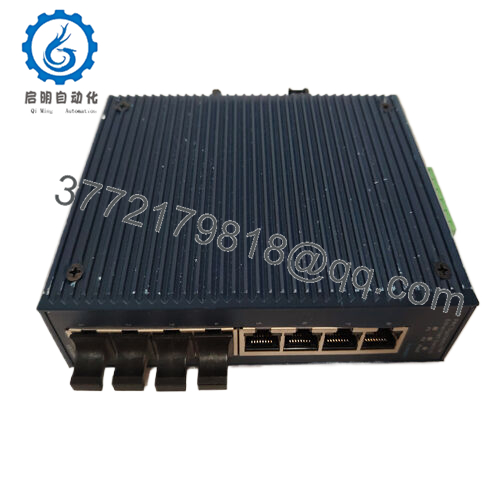
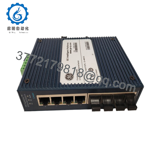
The GE IC800SSI420RP2 is a 4-channel analog output module within the VersaPoint distributed I/O family. It is designed to convert digital values from a controller into precise 4-20mA current signals, commonly used to position control valves, vary motor speeds through VFDs, or drive industrial actuators.
This module is known for its compact “slice” architecture, allowing for high-density I/O configurations in tight control cabinets. The IC800SSI420RP2 features independent channel protection and 12-bit resolution, providing the granularity needed for steady-state process control. While the VersaPoint line has moved toward legacy status, this module remains a critical component for maintaining existing installations in water treatment, HVAC, and light manufacturing.
Installation & Configuration Guide
Stage 1: Pre-Installation Preparation
- ⚠️ Safety First: Analog outputs often control active process elements. Place loops in manual mode at the HMI or bypass interlocks before swapping modules.
- Tools Required: Small flathead screwdriver (3.5 mm) for terminal release and an ESD wrist strap.
- Data Backup: Ensure you have the hardware configuration file for the VersaPoint station. Check the scaling parameters in the PLC logic (e.g., 0-30,000 raw counts for 4-20mA).
Stage 2: Removing the Old Module
- Identify the module in the VersaPoint stack.
- Press the release tabs at the top and bottom of the terminal block (the “connector” portion).
- Remove the terminal block without disconnecting the field wiring if possible—this saves significant re-commissioning time.
- Pull the module straight out from the DIN rail to disconnect it from the local bus.
Stage 3: Installing the New Module
- ESD Prep: Ground yourself. The VersaPoint bus interface is sensitive to static.
- Mounting: Snap the IC800SSI420RP2 onto the DIN rail, ensuring the side connectors align perfectly with the adjacent modules.
- Terminal Block: Re-insert the terminal block until it clicks into place.
- Check: Ensure the locking mechanisms are fully engaged to prevent vibration-related communication drops.
Stage 4: Power-On & Testing
- Apply power to the VersaPoint bus coupler.
- LED Check:
- D (Green): Bus communication active.
- E (Red): Peripheral fault (check for open loops or loss of 24V field power).
- Signal Test: Using the PLC software, force the output to 50% (12mA). Verify the field device moves to the expected position.
- Loop Check: Use a multimeter in series to confirm the signal is exactly 4.00 mA at 0% and 20.00 mA at 100%.

- IC800SSI420RP2
Frequently Asked Questions (FAQ)
Q: Does this module require an external 24V DC power supply for the loops?
A: Yes. While the logic power comes from the VersaPoint bus, the 4-20mA current loop typically requires 24V DC supplied through the power terminal module in the stack. If your “E” LED is on, the first thing to check is that 24V is present at the power segment.
Q: Can I use this module for a 0-10V signal?
A: No, the IC800SSI420RP2 is strictly for 4-20mA current outputs. If you need 0-10V, you must use the IC800SSV010RP2 or a similar voltage-specific module. Trying to convert current to voltage with a resistor is a “field fix” I don’t recommend for long-term reliability.
Q: What is the significance of the “RP2” in the part number?
A: “RP” stands for Remote Peripheral, and “2” usually denotes a specific hardware revision or packaging style for the VersaPoint series. Always match the full part number to ensure the backplane communication timings remain consistent with your existing configuration.
Q: Is this module hot-swappable?
A: VersaPoint modules are generally not recommended for hot-swapping while the bus is active. Removing a module breaks the local bus connection to all modules to its right. Power down the I/O station before replacing the module to avoid a bus fault.
Q: My output is stuck at 0mA despite the PLC command. Why?
A: Check for a “load open” fault. If the circuit is broken (e.g., a loose wire or a failed actuator coil), the IC800SSI420RP2 cannot drive current and will often flag an error. Measure the resistance of the loop; it must be under 500 Ω.


