
 WhatsApp: +86 16626708626
 Email:
  Phone: +86 16626708626
Description
3. Key Technical Specifications
| Parameter | Value |
|---|---|
| Manufacturer | General Electric (GE) |
| Model Number | IS200AEAAH2BJE |
| Product Type | Control Interface Board |
| Series | GE Mark VIe Speedtronic |
| Application | Gas and Steam Turbine Control |
| Mounting Method | Rack/Cabinet Mounted |
| PCB Coating | Industrial conformal coating |
| Communication Interface | Internal Mark VIe control bus |
| System Compatibility | GE Mark VIe architecture |
| Cooling Requirement | Forced-air cabinet cooling |
| Operating Environment | Industrial control cabinet |
| Diagnostic Capability | LED and software diagnostics |
| Protection Features | Industrial transient protection |
| Connector Style | Multi-pin industrial connectors |
| Redundancy Compatibility | System-dependent |
| Condition Options | New Original, New Surplus, Refurbished (tested) |
The IS200AEAAH2BJE belongs to the GE Mark VIe turbine control hardware family used in power generation and heavy industrial applications. Precise revision-level functionality should always be verified against the OEM documentation and existing cabinet configuration before installation.
4. Product Introduction
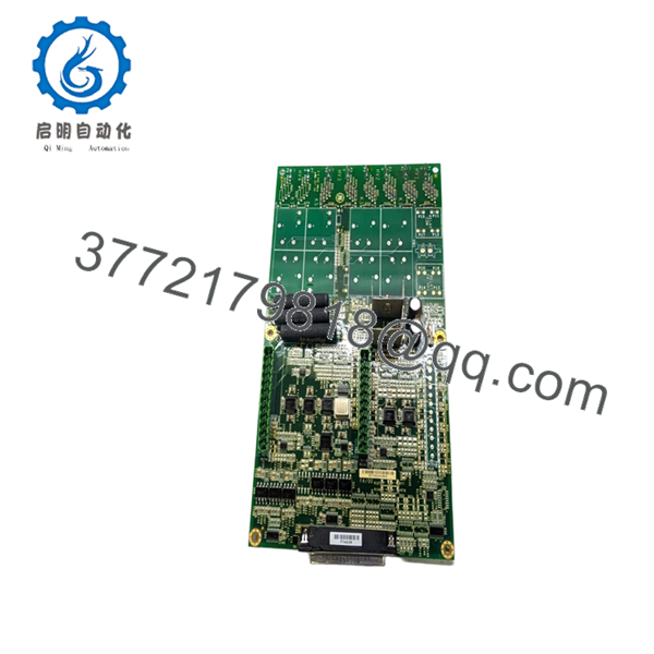
The GE IS200AEAAH2BJE is a control interface board used within GE Mark VIe turbine control systems. It operates inside industrial control cabinets where stable communication between processor, I/O, and protection subsystems is required.
In real plant environments, engineers usually replace this type of board during outage maintenance or fault recovery work where maintaining compatibility with existing Mark VIe hardware is more practical than performing a complete cabinet migration. Revision matching matters on these systems, especially in mixed-generation racks.

- IS200AEAAH2BJE
5. Installation & Configuration Guide
Stage 1: Pre-Installation Preparation (Estimated Time: 10 Minutes)
⚠️ Safety First
- Notify operations before taking the turbine or process offline.
- Bring the equipment to a verified safe shutdown state.
- Apply lock out/tag out procedures to all related power sources.
- Wait at least 5 minutes for capacitor discharge.
- Verify zero voltage using a Fluke 115 or equivalent multimeter.
Tools Required
- ESD wrist strap
- PH1 screwdriver
- Multimeter
- Wire labels
- Smartphone for documentation photos
- Flashlight
Data Backup
- Export current Mark VIe configuration from ToolboxST if available.
- Record:
- IP addresses
- Node assignments
- Rack positions
- Firmware revisions
- Photograph:
- Connector orientation
- Cable routing
- Jumper settings
- Grounding points
❗ Older turbine cabinets almost always contain undocumented field modifications from previous outages. Never assume the cabinet still matches the original drawings.
Stage 2: Removing the Old Module (Estimated Time: 5 Minutes)
- Remove the cabinet protective panel.
- Label all connectors individually.
- Disconnect cables carefully by gripping connector bodies only.
⚠️ Important
Do not pull on ribbon cables or field wiring directly. I’ve seen maintenance teams damage perfectly good connectors during rushed outages.
- Remove mounting hardware evenly.
- Pull the module straight outward without twisting.
Inspect the Cabinet Area
Check for:
- Dust buildup
- Loose hardware
- Burn marks
- Corrosion
- Bent connector pins
- Heat discoloration
⚠️ Keep the old module
Retain the original board until the replacement runs correctly under load.
Stage 3: Installing the New Module (Estimated Time: 10 Minutes)
- Wear a grounded ESD strap before handling the replacement board.
- Verify:
- Exact model number
- H2BJE revision suffix
- Connector layout
- Cabinet compatibility
❗ Configuration Clone (Critical)
Replicate all jumper settings and connector locations exactly from the original module.
This is one of the most common field mistakes. A connector shifted by one position or an overlooked jumper can create intermittent communication faults that waste an entire shift chasing phantom problems.
- Insert the IS200AEAAH2BJE evenly into the rack guides.
- Tighten mounting hardware carefully.
- Reconnect all cables fully and verify seating.
Self-Checklist
- Connector alignment verified
- Jumpers duplicated
- Hardware secured
- Grounding confirmed
- No loose objects inside cabinet
Stage 4: Power-On & Testing (Estimated Time: 15 Minutes)
Pre-Power Check
- Verify no shorts exist on supply rails.
- Confirm cabinet grounding continuity.
- Inspect connector seating one final time.
Power-On Procedure
- Energize the control rack only.
- Observe startup LEDs and diagnostic indicators.
- Connect engineering software and verify:
- Board recognition
- Communication status
- Firmware revision
- Rack health
- Restore configuration if required.
- Perform dry-run testing before returning the process to service.
⚠️ Firmware Revision Mismatch
This catches people constantly on legacy GE systems.
I’ve seen maintenance teams install the correct hardware revision physically, only to discover later that the firmware revision differed slightly from the rest of the cabinet. The rack booted, but intermittent communication alarms appeared under load.
Before ordering:
- Document firmware versions
- Match revisions carefully
- Verify ToolboxST compatibility
⚠️ Connector Placement Errors
Many Mark VIe connectors look nearly identical inside crowded cabinets.
One misplaced connector can create startup faults immediately or generate unstable behavior later during runtime.
Take clear photos before removal.
⚠️ Power Supply Margin
Do not assume older cabinet power supplies still deliver nameplate capacity.
Aging supplies drift over time, especially in turbine enclosures exposed to heat and vibration. Leave at least 20% headroom whenever possible.
⚠️ ESD Handling
Always use grounding protection.
I once watched a contractor unpack a spare GE control board onto cardboard during dry winter conditions. Static discharge damaged the board before installation even started. The cabinet faulted immediately during startup diagnostics.
Keep these checks in mind and you’ll save yourself 90% of typical rework time.
6. Frequently Asked Questions (FAQ)
Q1: Can the IS200AEAAH2BJE be hot-swapped?
No.
This board is not designed for live insertion or removal. Pulling the module under power can damage the backplane or interrupt cabinet communications.
Always isolate cabinet power before replacement.
Q2: Is the IS200AEAAH2BJE obsolete?
Yes.
This model belongs to the GE Mark VIe hardware family used in long-life industrial turbine systems. Most available inventory now comes from surplus channels, outage spare stock, or specialized industrial automation suppliers.
Stock availability can change quickly during major outage seasons.
Q3: Is this module genuinely new?
If listed as “New Original” or “New Surplus,” the board is typically unused OEM inventory sourced from surplus industrial stock.
You should still verify:
- Serial numbers
- Storage condition
- Connector wear
- Packaging integrity
- Revision labels
Test photos and startup videos should be available upon request.
Q4: Will replacing this board erase my control logic?
Normally, no.
Application logic in Mark VIe systems is generally retained elsewhere in the controller architecture. However, always back up the system before shutdown. Never assume the existing documentation is complete.
Q5: What is the most common installation mistake?
Connector misalignment and undocumented jumper settings.
Honestly, this causes more startup delays than defective hardware. People rush during outages and reconnect cables from memory instead of documentation.
Take photos before disconnecting anything.
Q6: Why do older GE control boards fail?
Typical causes include:
- Heat stress
- Dust contamination
- Aging capacitors
- Cabinet vibration
- Power supply instability
- ESD damage during handling
I’ve opened turbine cabinets that looked clean externally but had years of conductive dust buildup underneath the boards.
Q7: What testing should be completed before shipment?
A proper QC workflow should include:
- OEM traceability verification
- Serial number inspection
- Visual inspection for corrosion or rework marks
- Power-on testing using a compatible GE rack
- Communication handshake verification
- Insulation resistance testing using a 500 V Megger
- Burn-in testing under load for at least 24 hours
- Firmware and revision documentation
- ESD-safe packaging and QC sign-off
Verified fully functional under load testing. Test reports and startup videos should be available upon request.



