
 WhatsApp: +86 16626708626
 Email:
  Phone: +86 16626708626
Description
3. Key Technical Specifications
| Parameter | Value |
| Circuit Category | Digital input/output, power distribution, and pitch control card |
| System Compatibility | GE Wind / Speedtronic Mark VI turbine control platforms |
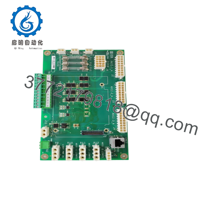
| Primary Auxiliary Assembly | Designed to host an auxiliary daughterboard (e.g., IS210BPPB) near its center |
| Mounting Configuration | Open PCB layout (no metal faceplate); corner mounting holes ringed with conductive material |
| Circuit Protection | 3 x Integrated high-capacity onboard fuses |
| Signal Inputs/Outputs | Multi-point wiring board terminals, pin-header connection blocks, and jack connectors |
| Onboard Active Components | Built-in FPGA array, high-durability diodes, power transistors, and resistors |
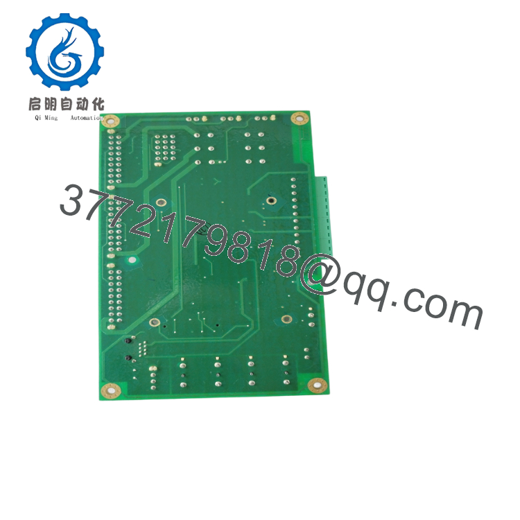
| Physical Profile | Rectangular card designed for direct chassis mounting on standoffs |
4. Product Introduction & Supply Chain Strategy
The GE Vernova IS200AEPCH1BAA is a highly specialized energy pitch center control and distribution module engineered specifically for GE’s heavy-duty industrial wind turbine and Speedtronic Mark VI systems. Lacking a traditional metal faceplate, this open-frame circuit board is mounted directly onto chassis standoffs inside the turbine hub or nacelle control enclosures. Its primary role is to regulate power and signal routing to the pitch axis drives, ensuring precise, high-speed adjustment of the turbine blade angles to optimize wind energy capture and protect the rotor assembly from overspeed damage.
Unlike simple passive termination boards, the IS200AEPCH1BAA is designed to host an active microprocessor-driven daughterboard (such as the IS210BPPB series). This dual-board stack utilizes onboard FPGAs and high-density discrete transistors to process localized encoder pulses and safety-critical I/O loops locally.
Because of its installation within the wind turbine’s pitch system, failure of this board completely disables pitch control, prompting an immediate safety trip. Sourcing this board as a certified New Surplus unit protects your operations from the risks of refurbished assemblies, such as microscopic solder fractures caused by high vibration or deteriorated capacitors that fail under thermal stress. Keeping 1–2 zero-hour units in your inventory ensures rapid, secure swaps, avoiding long OEM shipping times and high transport costs.
5. Installation & Technical Verification
Stage 1: Pre-Installation Prep
Safely lock out the wind turbine and ensure that all electrical supplies to the hub or pitch system cabinet are isolated. Verify that all auxiliary capacitor banks or backup battery modules associated with the pitch drives are fully discharged. Wear a grounded ESD wrist strap before unboxing the replacement board to safeguard its sensitive CMOS logic and FPGA arrays.
Stage 2: Physical Removal & Stacking
Carefully label and disconnect all wiring harnesses, jack connectors, and communication ribbon cables leading to the failed IS200AEPCH1BAA. If your original assembly utilizes a center-mounted daughterboard (like the IS210BPPB), gently unscrew the structural brackets and disconnect the board-to-board header interface. Mount this daughterboard onto the replacement IS200AEPCH1BAA, securing the mounting screws evenly to form a rigid, aligned stack.
Stage 3: Installation & Grounding
Align the conductive corner mounting holes of the new board with the cabinet standoff studs. These conductive rings provide essential frame-grounding connections to suppress electromagnetic interference (EMI); ensure the mounting screws are clean and tightened securely. Reattach all labeled communication and power plugs to their respective terminal strips and jack pins.
Stage 4: Testing & Calibration
Inspect the three onboard cartridge fuses with a digital multimeter to ensure they are fully intact before energizing the cabinet. Once cleared, restore control power to the pitch cabinet. Monitor the status LEDs on the daughterboard to confirm successful boot-up. Run the turbine system diagnostics through your engineering software suite to calibrate the pitch control parameters and verify that the feedback signal loops are reading correctly without faults.

- IS200AEPCH1BAA
- IS200AEPCH1BAA
6. Frequently Asked Questions (FAQ)
What is the role of the three integrated fuses on the IS200AEPCH1BAA?
The three onboard fuses provide localized overcurrent protection for the high-density power and signal distribution circuits. These fuses prevent high-voltage faults, surges, or field wiring shorts from reaching the sensitive digital logic on the motherboard and the attached processor daughterboard.
Why is the board designed without a front metal faceplate?
The IS200AEPCH1BAA is designed as an internal rack-mounted or panel-mounted distribution card. Because it resides within secure, sealed electrical cabinets in the turbine hub or nacelle, it does not require a rugged metal faceplate for external protection. This design also simplifies stacking with its daughterboard and reduces weight in vibrating, moving pitch enclosures.
Can the board be installed without the auxiliary daughterboard?
No. For applications requiring active turbine blade pitch control, the motherboard acts as the routing and power interface, while the auxiliary daughterboard (such as the IS210BPPB) handles the complex logic processing. Both boards must be joined as a cohesive system to execute the necessary control algorithms.
What warranty terms apply to this legacy GE component?
Every New Surplus IS200AEPCH1BAA module comes with our comprehensive 2-year operational warranty. If any defect occurs during this period, we provide immediate replacement or repair, protecting your maintenance budget from the short-term warranties typical of refurbished alternatives.



