
 WhatsApp: +86 16626708626
 Email:
  Phone: +86 16626708626
Description
3. Key Technical Specifications
| Parameter | Specification / Value |
| Manufacturer | GE (General Electric) |
| Part Number | IS200BPIAG1AEB |
| System Compatibility | Mark VI Speedtronic Control Systems |
| Application | Innovation Series Low Voltage Drives / Turbine Control |
| Nominal Input Voltage | 125 VDC |
| Gate Drive Output | Dual-channel isolated IGBT control |
| Communication Interface | Fiber-optic Link and High-Speed Backplane |
| PCB Coating | Conformal coated (Class 3C2 protection) |
| Operating Temperature | 0 to +50°C |
| Storage Temperature | −40 to +70°C |
| Dimensions | Standard Mark VI full-height form factor |
4. Product Introduction & Supply Chain Strategy
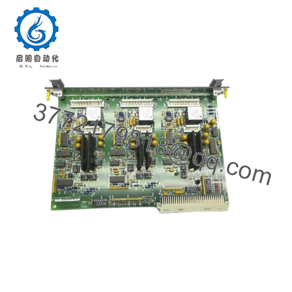
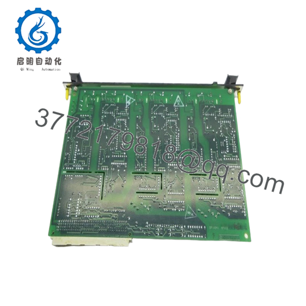
The GE IS200BPIAG1AEB is a high-performance Bridge Interface Board designed for the Mark VI Speedtronic turbine control and Innovation series drive systems. It acts as the critical physical and electrical link between the digital control core and the Insulated Gate Bipolar Transistor (IGBT) power inversion bridge, converting low-voltage logic signals into high-current gate drives while maintaining strict electrical isolation. This module is standard equipment in large-scale power generation, gas turbine control, and heavy industrial motor drive applications where precision timing and high noise immunity are non-negotiable.
From a lifecycle management perspective, procuring this board as a New Surplus unit is a calculated risk-mitigation strategy. Because GE has designated the legacy Mark VI series as mature or obsolete, relying on standard factory lead times is no longer viable. Purchasing verified New Surplus stock eliminates the extreme lead times associated with specialized legacy components. It drastically lowers Total Cost of Ownership (TCO) compared to emergency OEM sourcing, while removing the catastrophic failure risks linked to unverified, third-party repaired alternatives.
- IS200BPIAG1AEB
- IS200BPIAG1AEB
5. Installation & Configuration Guide
Stage 1: Pre-Installation (Prep & Safety)
- Execute complete lock-out/tag-out (LOTO) procedures on both the control cabinet power supplies and the high-voltage AC/DC bus feeding the IGBT bridge.
- Verify with a calibrated digital multimeter that the 125 VDC and 24 VDC rails are fully discharged to 0 V before opening the housing.
- Equip all personnel with a grounded, corded ESD wrist strap connected to the cabinet chassis.
- Document the exact revision letter, hardware modifications, and jumper settings of the existing board using a high-resolution camera.
Stage 2: Removal
- Carefully disconnect all fiber-optic lines, labeling them clearly to prevent Tx/Rx inversion during reassembly.
- Unfasten the retaining screws holding the board faceplate to the rack assembly.
- Pull the ejector tabs outward simultaneously to back the board out of its backplane connector.
- Slide the board out along the guide rails, handling it strictly by the edges to prevent static discharge to surface-mounted components.
Stage 3: Installation (Clone & Seat)
- Extract the new IS200BPIAG1AEB module from its anti-static packaging inside an ESD-protected zone.
- Inspect the hardware revision suffix (1AEB) and mirror all hardware jumpers and DIP switch positions from the old board exactly.
- Align the module with the card guide rails and slide it smoothly into the slot until the rear connectors meet the backplane.
- Press the ejector handles inward firmly to seat the card completely, then secure the front panel retaining screws.
- Reconnect all fiber-optic and copper wiring harnesses to their designated terminals according to your pre-removal labels.
Stage 4: Power-On & Testing
- Conduct a final visual verification to ensure no loose wires or tools remain inside the chassis.
- Re-energize the low-voltage control power circuit while keeping the main power bridge isolated.
- Observe the diagnostic LEDs on the faceplate: the green power LED must remain solid, and the red fault LED must remain dark.
- Connect the system diagnostic software to verify that the slot address updates correctly and that the communication handshake with the control processor is successful.
6. Firmware/Software Versions & Upgrade Notes
The IS200BPIAG1AEB relies on programmable logic devices matched to the functional revision level indicated by its 1AEB suffix. When executing a replacement, the hardware revision level of the new module must match the existing system configuration within the Toolbox software environment.
Deploying an incorrect hardware revision can cause immediate configuration mismatches, leading to backplane communication failures, protocol dropouts, or phase synchronization errors on the IGBT gate drives. Do not attempt to flash firmware or alter EEPROM configurations on this board mid-operation unless instructed by a qualified systems engineer. Always pull a complete system diagnostic backup before pulling or inserting any Mark VI backplane module to prevent accidental parameter loss.
7. Frequently Asked Questions (FAQ)
What exactly is the condition of this GE IS200BPIAG1AEB unit?
This item is a Brand New Surplus unit. It is not second-hand, it has never been installed in an active industrial system, and it has not undergone third-party component repairs. It is original OEM inventory that has been stored in climate-controlled environments and opened only for our strict inbound quality control and serialization verification processes.
Why is New Surplus inventory preferable to a refurbished alternative?
Refurbished industrial electronics present massive hidden risks, particularly degraded electrolytic capacitors, weakened optocouplers, and invisible thermal fatigue on the PCB layers. While a refurbished module might pass a basic power-on test, it frequently fails under high thermal load or industrial vibration. Choosing New Surplus ensures original OEM lifespans (typically 10 to 15 years), preventing unexpected downtime events that can easily cost tens of thousands of dollars per hour.
Is this specific model still actively manufactured by GE?
No. The GE Mark VI series components, including the IS200BPIAG1AEB, are legacy hardware that has transitioned past active production phases. Because they are obsolete, maintaining 1 or 2 units on-site as buffer stock is an important insurance policy to prevent extended plant outages when an online module eventually reaches its end-of-life.
Do I need to reconfigure any software variables when installing this board?
As a bridge interface board, the module primarily handles hardware signal translation and gating execution. However, you must match all physical jumper configurations and DIP switch addresses found on your original board. If the system software detects a revision mismatch between the old unit and the replacement, a configuration download via GE Toolbox may be required to sync the hardware profile.
What kind of warranty coverage accompanies this module?
We back this New Surplus IS200BPIAG1AEB with a comprehensive commercial warranty that matches or exceeds the original OEM coverage period. This gives procurement teams and engineering managers full financial protection and peace of mind, completely eliminating the gamble associated with the short 30-day warranties typical of used or refurbished equipment dealers.


