
 WhatsApp: +86 16626708626
 Email:
  Phone: +86 16626708626
Description
3. Key Technical Specifications
| Parameter | Value |
| Manufacturer | General Electric (GE) |
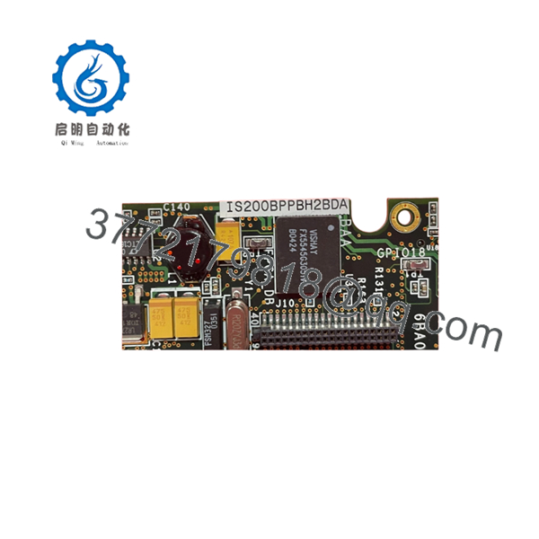
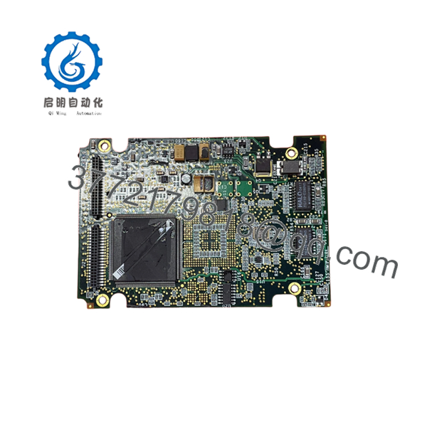
| Part Number | IS200BPPBH2BDA |
| Functional Acronym | BPPB |
| Revision Level | H2BDA |
| System Compatibility | GE Innovation Series Low/Medium Voltage Drives |
| Gating Output Channels | Up to 6 independent SCR/Thyristor gate drives |
| Feedback Monitoring | Integrated bridge voltage and temperature telemetry |
| Isolation Rating | Galvanic isolation for high-voltage power components |
| Operating Temperature | 0 to 50 °C |
| Storage Temperature | −40 to +70 °C |
| Humidity Resistance | 5% to 95% relative humidity (non-condensing) |
4. Product Introduction & Supply Chain Strategy
The GE IS200BPPBH2BDA is a Bridge Personality (BPPB) board designed for GE’s Innovation Series drive and control architectures. Positioned directly within the power conversion stack, this card acts as the critical physical and electrical interface between the low-voltage digital control processors and the high-power SCR or thyristor bridge assembly. It handles the precise distribution of gating signals to control power flow while conditioning high-voltage feedback variables—such as bridge temperatures and line voltages—back into safe, logic-level data streams.
Maintaining this exact board configuration as a New Surplus asset is an essential risk-mitigation strategy for facilities operating legacy Innovation Series drives. Because these components have transitioned to end-of-life (EOL) status, lead time variability can halt production lines for weeks if a breakdown occurs. Securing a certified New Surplus board avoids the severe operational failures tied to refurbished alternatives, such as compromised galvanic isolation layers or degraded optocouplers that risk exposing sensitive control electronics to destructive high-voltage spikes.
5. Installation & Configuration Guide
Stage 1: Pre-Installation (Prep & Safety)
Isolate the entire drive system from the primary 3-phase incoming power feeds and execute strict lock-out/tag-out (LOTO) procedures. Allow a minimum of 20 minutes for the internal DC bus link capacitors to discharge completely, and verify zero voltage using a calibrated digital multimeter. Fasten a grounded ESD wrist strap to your arm, clamping the opposite end to the unpainted drive frame chassis. Document all fiber optic and wire-harness connections using high-resolution photography.
Stage 2: Removal
Carefully unplug the multi-pin ribbon cables, discrete gate-lead wires, and fiber-optic cables from the face of the BPPB module. Undo the hex nuts or screws securing the PCB to its mounting standoffs on the bridge framework. Gently pull the card straight outward from its alignment pins to avoid cracking the surrounding fiber-optic brackets or scratching the board’s traces, and place the card into a static-shielded storage bag.
Stage 3: Installation (Clone & Seat)
Verify that the replacement IS200BPPBH2BDA board matches the exact hardware layout and revision layer of the old module. Inspect the onboard DIP switches and micro-jumpers, matching their positions to the configuration documented in Stage 1 to ensure correct drive identification and attenuation properties. Align the board with the mounting standoffs, press evenly until seated, and secure all mounting hardware. Reattach the gating wires and communication cables to their corresponding terminal blocks.
Stage 4: Power-On & Testing
Conduct a preliminary low-voltage control check by applying auxiliary power before energizing the main three-phase bridge infrastructure. Observe the startup LED diagnostic sequence on the board’s front faceplate. If the green status indicator stabilizes and no synchronization or gate-fault errors register on the master HMI, slowly ramp up the primary bridge voltages to execute an active loop test.

- IS200BPPBH2BDA
- IS200BPPBH2BDA
6. Firmware/Software Versions & Upgrade Notes
The IS200BPPBH2BDA functions primarily as a hardware personality layout map and does not contain user-modifiable microcode firmware blocks. However, its onboard logic circuits and scaling resistors are strictly tuned to specific firmware revisions operating within the primary drive control processor (such as the Control Assembly Board).
When replacing an older revision card with the H2BDA variant, verify that your master system application files support the H2BDA configuration data structures. Incorrect parameter pairing in the drive setup files can cause unexpected gate-monitor faults or incorrect thermal calibration scaling factors, preventing the drive from reaching full rated load capacity.
7. Frequently Asked Questions (FAQ)
- What makes the “H2BDA” revision code specific compared to other BPPB variants? The “H2BDA” alphanumeric suffix designates the exact hardware revision loop, components list, and resistor scaling profiles chosen by GE for this specific drive size and voltage class. Substituting this module with an alternative revision layer can introduce different scaling parameters, causing the primary drive controller to read incorrect bridge telemetry data.
- Why should we choose a New Surplus BPPB board over a repaired or refurbished card? Selecting New Surplus ensures that the card’s voltage isolation barriers, high-speed gate transformers, and optical components are at 100% operational capacity with zero thermal wear. Refurbished thyristor interface cards frequently have latent stress damage from previous over-current events, increasing the risk of early failure that could destroy the high-power bridge assembly.
- Can this bridge interface card be hot-swapped while the drive is running? Absolutely not. The physical and electrical contacts on the IS200BPPBH2BDA tie directly into high-speed gating networks and high-voltage sense points. Attempting a hot-swap while the system is live will induce severe arc-flash risks, completely destroy the module’s electronic components, and trigger an immediate catastrophic drive failure.
- What procedures are used to confirm that this obsolete part is genuinely new? Every board undergoes a strict inbound verification process. Our technicians check the authenticity of the factory anti-static packaging, examine the board for any solder modifications or terminal screw marking residue, and trace the unit’s supply chain history to guarantee it has never been mounted in an active system.
- What type of warranty coverage applies to this New Surplus module? This module comes with a full 1-year warranty that starts from the day of invoice. This policy matches the original factory warranty framework, giving your procurement and maintenance teams dependable asset protection without requiring expensive OEM support agreements.


