
 WhatsApp: +86 16626708626
 Email:
  Phone: +86 16626708626
Description
3. Key Technical Specifications
| Parameter | Specification | |
|---|---|---|
| Manufacturer | General Electric | |
| Product Series | Mark VI IS200 / Innovation Series | |
| Functional Acronym | DSFC (Driver Shunt Feedback Card) | |
| Board Function | IGBT Gate Driver / Shunt Feedback | |
| PWM Current Rating | 1000A / 1800A | |
| AC Input Voltage | 600V LL rms | |
| System Configuration | 3 boards per 1000A system | |
| LED Indicators | 5 onboard LEDs (including “LINK ABOVE 50V”) | |
| Protection | MOV (Metal Oxide Varistor) for surge protection | |
| Isolation | Galvanic and optical isolation | |
| Configurable Hardware | Jumper pins (PL, PL1, PL2) for customization | |
| Physical Dimensions | 2 in (H) × 3 in (L) | |
| Mounting | Precision mounting with orientation requirements | |
| Compatibility | Innovation Series™ source bridges and AC drives | |
| Reference Manual | GEI-100263 | |
| Operating Temperature | -40°C to +70°C | |
| Country of Origin | United States |
4. Product Introduction & Supply Chain Strategy
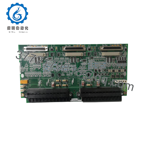
The GE IS200DSFCG1A is a Driver Shunt Feedback Board (DSFC) engineered for GE’s Speedtronic Mark VI platform and Innovation Series drives. It delivers precise current feedback through integrated shunt resistors, drives IGBT gates for power conversion, and provides MOV surge protection for high-reliability industrial drive applications. The board features galvanic and optical isolation to ensure noise immunity in high-energy environments, with five onboard LEDs delivering real-time diagnostic visibility.As a New Surplus unit, this board represents critical inventory for maintaining legacy Mark VI drive systems. GE has transitioned focus to newer platforms, making the IS200DSFCG1A increasingly scarce. The Total Cost of Ownership (TCO) heavily favors new surplus acquisition: a refurbished DSFC board may save 15-20% upfront, but prior thermal cycling and capacitor aging create latent failure risks that can cascade into drive system faults costing $250,000+ in lost production. This New Surplus unit provides 10-15 years of service life expectancy with full warranty protection — essential insurance for baseload power generation and critical process drives.
5. Installation & Configuration Guide
Stage 1: Pre-Installation (Prep & Safety)
- Lock-out/Tag-out: Isolate the drive system from all power sources — including 600V AC input, 24V control power, and DC bus. Verify zero energy with a calibrated multimeter.
- System Documentation: Photograph all existing jumper positions (PL, PL1, PL2) and LED states. Document daisy-chain configuration if replacing one of multiple DSFC boards in an 1800A system.
- ESD Protocol: Attach grounded wrist strap to the drive chassis earth bar. The IS200DSFCG1A contains sensitive ICs vulnerable to static discharge.
- Tool Preparation: Phillips screwdriver, torque screwdriver (set to manufacturer specifications for terminal connections), and anti-static mat.
Stage 2: Removal
- Power Verification: Confirm all LEDs are extinguished and DC bus capacitors are fully discharged (minimum 5-minute wait after power-down).
- Connector Extraction: Carefully remove all signal connectors. Note the orientation of the “LINK ABOVE 50V” LED — this indicates high-voltage presence even when control power is off.
- Board Extraction: Loosen mounting screws evenly. Grasp the board by the edges (never by components) and pull straight out to avoid bending backplane pins. Inspect the UGB and UEB metal components for thermal discoloration.
Stage 3: Installation (Clone & Seat)
- Jumper Replication: Configure PL, PL1, and PL2 jumpers exactly as the removed board. These customize current sensing thresholds and fault detection behavior.
- Board Seating: Align the IS200DSFCG1A with the drive backplane. The board must seat fully — gaps between the PCB and connector housing indicate incomplete insertion.
- Daisy-Chain Verification: In 1800A systems, verify the daisy-chain communication link between DSFC boards is properly re-established per GEI-100263.
Stage 4: Power-On & Testing
- Continuity Check: Verify no shorts between gate drive outputs and ground before applying power.
- Power-Up Sequence: Apply control power first, observe the 5 LEDs for proper initialization sequence. The “LINK ABOVE 50V” LED illuminates when DC bus exceeds 50V.
- Functional Verification:
- Monitor shunt feedback signals for proper current scaling
- Verify IGBT gate drive waveforms with oscilloscope (if available)
- Test fault detection circuits via simulation
- Documentation: Record serial number, installation timestamp, and jumper configuration in the plant’s CMMS system.
6. Firmware/Software Versions & Upgrade Notes
The IS200DSFCG1A is primarily a hardware analog/digital hybrid board with limited onboard firmware. However, integration with the Mark VI control system requires careful attention to compatibility:
| Component | Compatibility Consideration |
|---|---|
| Mark VI Control Firmware | DSFC boards must match the revision level expected by the drive control processor |
| Innovation Series Bridges | Verify PWM switching frequency compatibility (affects shunt feedback scaling) |
| Current Sensing Calibration | Jumper settings (PL/PL1/PL2) must align with the application code current limits |
| Daisy-Chain Communication | 1800A systems require matched DSFC revisions for proper inter-board communication |
Critical Warning: When replacing a failed IS200DSFCG1A, do not simultaneously upgrade Mark VI control firmware. Changing both hardware and software in the same maintenance window creates compound failure risk. If the existing board operates with control firmware V5.x, maintain that version until the new DSFC board is proven operational. Document the jumper configuration of the old module before removal — incorrect PL/PL1/PL2 settings can cause current sensing errors and premature drive trips.

- IS200DSFCG1A
7. Frequently Asked Questions (FAQ)
Q: Why is this New Surplus unit more expensive than refurbished alternatives?
A: Refurbished DSFC boards typically carry 30-60 day warranties and have unknown thermal histories — many have operated for years in high-temperature drive cabinets. This New Surplus unit is factory-original with zero prior runtime, offering 10-15 years of service life and a 12-month warranty. The price premium eliminates the risk of a 500 “savings” triggering a 300,000 drive system failure.
Q: Is the IS200DSFCG1A still in production?
A: No. The Mark VI IS200 series is in mature lifecycle phase, with GE focusing on Mark VIe and newer platforms. The IS200DSFCG1A is classified as EOL (End of Life). This is genuine New Surplus inventory — original OEM manufacturing, never deployed. For critical drive applications, we recommend strategic hoarding of 1-2 spare units as buffer stock.
Q: Can I hot-swap this board while the drive is running?
A: Absolutely not. The IS200DSFCG1A carries 600V AC-class potentials and drives high-power IGBTs. Hot-swapping risks arc flash, catastrophic drive damage, and personnel injury. Always execute Lock-out/Tag-out procedures and ensure DC bus discharge before replacement.
Q: How many DSFC boards do I need for my system?
A: System configuration determines board count: 3 DSFC boards are required for a 1000A system, while 6 DSFC boards are needed for an 1800A system. In 1800A configurations, the boards are daisy-chained for coordinated control.
Q: Will my existing drive programming remain intact after replacement?
A: Yes. The IS200DSFCG1A is a feedback/driver board — it does not store application parameters or control logic. Your programming resides in the Mark VI control processor. However, you must replicate the jumper configuration (PL, PL1, PL2) exactly to maintain current sensing calibration and fault detection thresholds.
Q: What is your warranty coverage?
A: We provide a 12-month replacement warranty against manufacturing defects. This covers functional failure under normal operating conditions (-40°C to +70°C, nominal voltage ranges). Physical damage, ESD damage from improper handling, or voltage surge events exceeding MOV ratings are excluded. Each unit ships with a QC Test Report documenting full functional verification.
Q: How do I verify this is genuine GE and not counterfeit?
A: Each unit ships with OEM traceability documentation including the original GE packing slip reference and serial number verification. Authentic IS200DSFCG1A boards feature specific GE factory markings, the characteristic PCB layout with UGB/UEB metal components, and proper “LINK ABOVE 50V” LED labeling. We perform incoming inspection for counterfeit indicators including incorrect component placement, anomalous solder mask colors, and non-GE IC markings.


