
 WhatsApp: +86 16626708626
 Email:
  Phone: +86 16626708626
Description
3. Key Technical Specifications
| Parameter | Value |
|---|---|
| Model Number | IS200DSPXH2B |
| Manufacturer | General Electric |
| Product Family | EX2100 / Mark VI |
| Product Type | Digital Signal Processor Control Board |
| Board Role | DSP Control Processing |
| Processor Frequency | 60 MHz |
| Memory Architecture | SRAM, FLASH, Add-Only Memory |
| Interrupt Inputs | 4 External Interrupts |
| Serial Interfaces | 4 P1 Interfaces |
| Front Status Indicators | 2 LEDs |
| Mounting Method | Backplane rack mounting |
| Conformal Coating | Yes |
| Documentation Reference | GEI-100267B |
| Operating Environment | Industrial control cabinet |
| Condition | New Original / New Surplus |
| Warranty | 12 months |
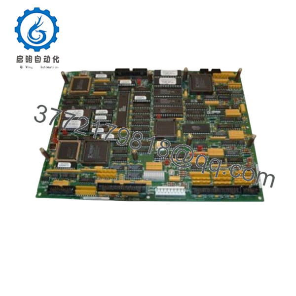
IS200DSPXH2B is identified as a Digital Signal Processor Control Board used in GE EX2100 and Mark VI environments. Public technical references list a 60 MHz processor and DSP architecture details.
4. Product Introduction
The GE IS200DSPXH2B is a Digital Signal Processor (DSP) Control Board used in GE EX2100 excitation systems and Mark VI turbine control environments. It executes digital signal processing tasks and custom logic functions within turbine and drive applications.
In field deployments, DSP boards become critical during outage windows because they sit directly in the processing chain. A failed DSP card can create confusing symptoms—communication faults, unstable control behavior, or startup issues that initially look like I/O problems. Matching board revisions matters more than many maintenance teams expect.
- IS200DSPXH2B
5. Installation & Configuration Guide
Stage 1: Pre-Installation Preparation (Estimated Time: 10 minutes)
⚠️ Safety First: Notify operations of downtime. Confirm the turbine or process is in a safe state. Apply lockout/tagout procedures. Remove cabinet power and wait 5 minutes for discharge.
Tools Required
- ESD wrist strap
- PH1 screwdriver
- Fluke 115 multimeter
- Wire labels
- Smartphone for photographs
- ESD work mat
Data Backup
- Export current configuration and logic backups.
- Document IP addresses and controller settings.
- Photograph board positions and cable routing.
- Capture DIP and jumper positions.
- Record board revision labels.
⚠️ I have opened EX2100 cabinets where field modifications never made it into engineering records. Trust photos more than assumptions.
Stage 2: Removing the Old Module (Estimated Time: 5 minutes)
- Open cabinet access panels.
- Label all connections before removal.
- Disconnect connectors carefully.
- Release board retainers.
- Pull straight outward.
⚠️ Never wiggle the board side-to-side.
I watched a technician damage a backplane connector once trying to force a board out. Fifteen-minute maintenance became a two-day outage.
Inspect:
- Bent pins
- Heat damage
- Corrosion
- Dust buildup
- Loose hardware
⚠️ Keep the original module nearby until startup is complete.
Stage 3: Installing the New Module (Estimated Time: 5–10 minutes)
- Wear ESD protection.
- Verify exact part number: IS200DSPXH2B
- Configuration Clone (Crucial): Match jumper and configuration settings exactly.
- Align card guides carefully.
- Insert evenly until seated.
- Reconnect all wiring.
Self-Checklist:
[ ] Jumpers match
[ ] Wiring secure
[ ] Board seated
[ ] Retainers locked
⚠️ This is the most common rookie mistake, but it happens constantly. Take a picture before removal. I can’t stress this enough.
Stage 4: Power-On & Testing (Estimated Time: 10 minutes)
Pre-Power Check
Verify no short exists on the 24 V rail.
Power sequence:
- Energize rack only
- Observe LED startup sequence
- Verify RUN indications
- Connect engineering workstation
- Confirm communication status
- Perform dry-run I/O tests
Expected status:
- Green RUN = Normal
- Red ERR = Fault
⚠️ Troubleshooting Note:
Solid fault indications after startup frequently point toward firmware or revision compatibility issues.
Technical Pitfall & Survival Guide
❗ Firmware Revision Mismatch
This one creates expensive confusion.
I saw a replacement board installed during a scheduled outage that immediately produced communication timeout alarms. Everyone chased network issues first.
The actual cause? Firmware revision drift.
Avoidance:
- Record firmware before shutdown
- Match revisions whenever possible
- Request specific revision ranges when ordering
❗ DIP Switch / Jumper Errors
Factory defaults rarely match plant installations.
Take pictures before removal.
Seriously.
❗ Connector and Wiring Variations
GE hardware families evolved over time.
Always verify:
- Connector orientation
- Shield grounding
- Wiring diagrams
- Pin assignments
Never wire from memory.
❗ Power Consumption
DSP boards rarely operate alone.
Calculate total rack loading and maintain a 20% margin.
A DSP board itself may not overload a supply, but ten added modules over several years can.
❗ ESD Damage
I watched an engineer grab a board during dry winter conditions without a wrist strap. Immediate startup failure followed.
That mistake cost more than the labor budget for the entire outage.
Use:
- Grounded wrist straps
- ESD-safe surfaces
- Anti-static handling procedures
Keep these checks in mind and you’ll save yourself 90% of typical rework time.
6. Frequently Asked Questions (FAQ)
Q1: Can I hot-swap GE IS200DSPXH2B?
No.
Do not hot-swap this board. GE rack systems of this generation were not intended for powered insertion. Backplane damage and communication faults can result.
Q2: Is IS200DSPXH2B obsolete?
Yes.
Production is no longer active. Available inventory typically comes through controlled surplus channels and specialist stock providers. Multiple industrial listings identify current availability as surplus inventory rather than factory production.
Q3: Is this actually new inventory?
Usually “New Original” means unused OEM surplus inventory.
Request:
- Date codes
- Serial numbers
- Packaging photos
- Test reports
Q4: Does IS200DSPXH2B support EX2100 systems?
Compatibility depends on revision level. Some references note interface limitations within certain EX2100 implementations. Verify against OEM documentation before installation.
Q5: Will replacing this board erase my control logic?
Normally no.
Logic usually resides elsewhere in the control architecture. Still, create backups before touching hardware.
I’ve seen undocumented field edits create surprises.
Q6: How do you test inventory before shipment?
Inspection follows this sequence:
- OEM source verification
- Serial and anti-counterfeit checks
- Visual inspection for corrosion, scratches, yellowing, and repair marks
- Functional testing on compatible hardware where available
- Communication verification
- 500 V Megger insulation test (>10 MΩ)
- QC approval and ESD packaging
Photos and startup videos are available upon request.
Q7: Why are prices inconsistent between suppliers?
Traceability changes everything.
Current listings range from approximately 5,995 to over 7,700 depending on inventory condition, warranty terms, and documentation availability.


