
 WhatsApp: +86 16626708626
 Email:
  Phone: +86 16626708626
Description
3. Key Technical Specifications
| Parameter | Value |
|---|---|
| Manufacturer | General Electric (GE) |
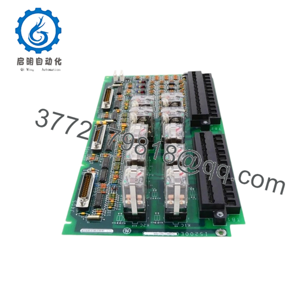
| Model Number | IS200ECTBG1ABB |
| Functional Acronym | ECTB |
| Product Type | Excitation Contact Terminal Board |
| System Series | Mark VI / EX2100 |
| System Mode | Redundant only |
| Auxiliary Contact Inputs | 6 |
| Contact Input Voltage | 70 VDC |
| Trip Contact Outputs | 2 |
| Relay Outputs | 4 Form-C contacts |
| Controlled By | EMIO Board |
| Companion Boards | EPCT, EXTB, EACF |
| Power Source | M1 and M2 redundant supplies |
| Application | Gas, steam, and wind turbine excitation systems |
| Manual References | GEI-100457, GEH-6632 |
| Product Status | Legacy / Obsolete platform |
The IS200ECTBG1ABB is an Excitation Contact Terminal Board used in GE Mark VI turbine control systems and EX2100 excitation architecture. It provides excitation contact monitoring, relay handling, and lockout functions under EMIO control.
4. Product Introduction
GE IS200ECTBG1ABB is an Excitation Contact Terminal Board designed for GE Mark VI turbine control and EX2100 excitation applications. The board interfaces with auxiliary contact circuits, trip circuits, and relay outputs used in gas, steam, and wind turbine systems.
In field deployments of EX2100 systems, this board typically handles lockout status and excitation signal management. Plants keep spare ECTB boards because excitation failures can force unit trips and create expensive generation downtime. Verify board revision and redundancy configuration before replacement.

- IS200ECTBG1ABB
5. Installation & Configuration Guide
Stage 1: Pre-Installation Preparation (Estimated Time: 10 minutes)
⚠️ Safety First: Notify operations personnel of downtime. Confirm turbine safe state. Apply lockout/tagout procedures. Remove cabinet power and wait 5 minutes minimum for discharge.
Tools Required
- Grounded ESD wrist strap
- PH1 screwdriver
- Fluke 115 multimeter
- Wire labels
- Smartphone for photographs
- ESD work surface
Data Backup
- Export EX2100 configuration if available
- Record terminal designations
- Photograph board position and wiring
- Photograph all jumper settings and cable orientation
- Document associated EMIO slot location
I’ve seen technicians skip photos because they “know the cabinet layout.” Six hours later they are tracing conductors one at a time.
Stage 2: Removing the Old Module (Estimated Time: 5 minutes)
- Remove cabinet access panel.
- Label all terminal wiring before disconnecting.
- Release retaining hardware.
- Pull board straight outward.
- Inspect connector surfaces and backplane condition.
⚠️ Note: Keep the original board until startup verification finishes successfully.
Stage 3: Installing the New Module (Estimated Time: 10 minutes)
- Attach ESD strap before handling electronics.
- Verify model: IS200ECTBG1ABB
- Configuration Clone (Crucial): Duplicate jumper settings and installation orientation exactly from photographs.
- Insert evenly into guide rails.
- Secure retaining hardware.
- Reconnect wiring using controlled torque.
Self-Checklist:
- Model verified
- Wiring secured
- Connectors seated
- Retention hardware tightened
- Jumpers confirmed
❗This is the most common rookie mistake, but it happens constantly. Take a picture before you pull it.
Stage 4: Power-On & Testing (Estimated Time: 10 minutes)
Pre-Power Check
- Use multimeter to verify no short on supply rails
- Verify cabinet grounding continuity
Power-up steps:
- Energize control cabinet only
- Observe diagnostics and status LEDs
- Connect ToolboxST or applicable engineering software
- Verify board recognition and I/O status
- Test relay and contact status functions
- Perform dry-run verification before field reconnection
⚠️ Troubleshooting Note: If communication faults occur immediately after startup, inspect redundancy wiring and firmware compatibility before replacing additional hardware.
I’ve watched technicians replace two EMIO modules before finding one partially seated connector.
6. Frequently Asked Questions (FAQ)
Q1: Can I hot-swap this module?
No. Do not hot-swap IS200ECTBG1ABB. Mark VI hardware was not designed for arbitrary live insertion. Pulling terminal boards under power can damage contacts or create excitation faults.
Kill power first.
Q2: Is this model obsolete, and can I still buy genuine units?
Yes. IS200ECTBG1ABB belongs to a mature Mark VI generation and many units now circulate through surplus channels. New Original and New Surplus inventory still appears, but stock changes constantly.
Q3: What is the direct replacement if this board becomes unavailable?
There is no guaranteed drop-in replacement outside the exact board family. Hardware revisions and system architecture vary. Verify with GE documentation before substitution.
Q4: Will I lose application logic during replacement?
No. The ECTB board functions as an excitation interface component. Control logic normally resides elsewhere in the Mark VI architecture.
Still perform configuration backups before touching hardware.
Q5: Why are New Surplus boards often cheaper than OEM pricing?
Most available inventory comes from plant shutdowns, strategic spare inventories, or decommissioned systems.
Lower cost does not automatically indicate counterfeit material. Inspection history matters more than price.
Q6: How do you verify quality before shipment?
Our SOP process follows practical field methods:
Inbound Inspection & Traceability
- Verify OEM source documents
- Inspect labels and serial identifiers
- Check for corrosion, UV yellowing, rework marks
- Audit included paperwork
Live Functional Testing
- Install onto genuine Mark VI test hardware
- Verify startup sequence
- Simulate I/O signals
- Communication handshake verification
- Continuous operation >24 hours
Electrical Testing
- 500 V Megger insulation resistance >10 MΩ
- Ground continuity checks
- Electrical parameter verification
Firmware Verification
- Record hardware revision
- Photograph jumper and switch settings
Final QC
- Inspector sign-off
- ESD packaging
- Heavy-duty carton packaging
- QC date labeling
Test photos and videos are available upon request.
Q7: Any replacement traps I should watch for?
Absolutely.
❗Firmware revision mismatches create communication faults.
❗DIP switch settings and jumpers must match exactly.
❗Check terminal assignments carefully.
Even among similar Mark VI hardware revisions, small connector differences can create large headaches. Never wire from memory.
I once saw a technician swap a module and spend two days troubleshooting a “failed” board. The problem was one missed configuration jumper.
Keep these checks in mind and you’ll save yourself 90% of typical rework time.


