
 WhatsApp: +86 16626708626
 Email:
  Phone: +86 16626708626
Description
3. Key Technical Specifications
- Manufacturer: GE (General Electric)
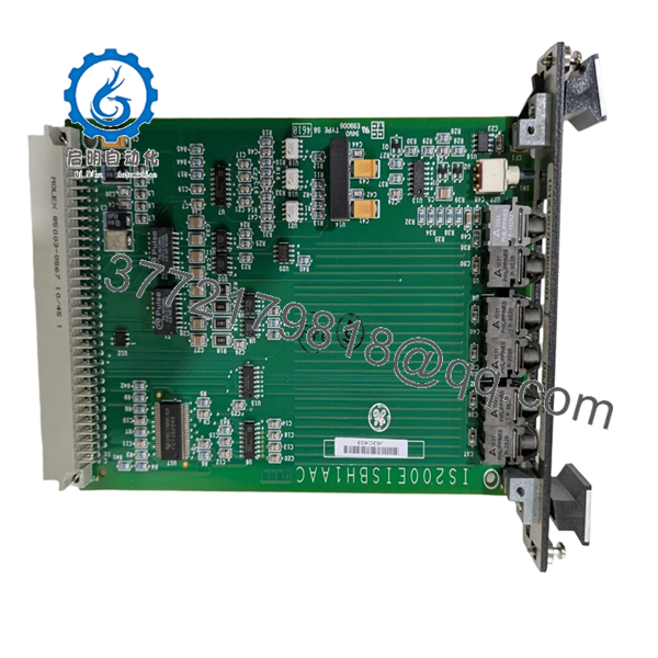
- Model Number: IS200EISBH1AAC
- Functional Acronym: EISB
- Product Type: Exciter ISBus Board
- Series: GE Mark VI IS200 / EX2100
- Primary Function: Communication interface between exciter modules and Mark VI controllers
- Bus Type: ISBus (Intelligent Systems Bus)
- Mounting: VME rack assembly
- Communication Interface: Fiber optic feedback signal interface
- Fiber Channels: Generator field voltage/current, exciter voltage/current, ground detect signals
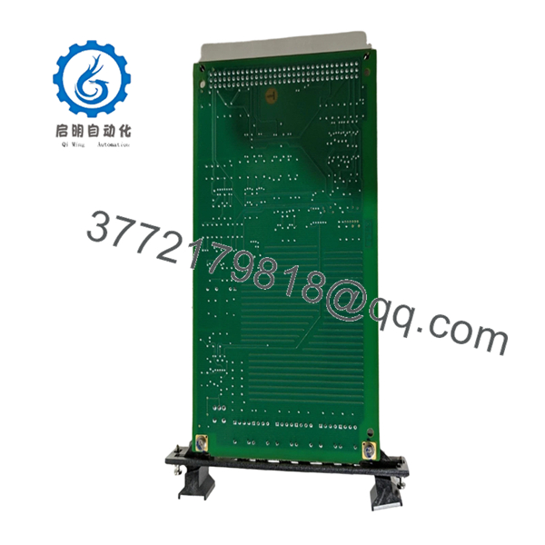
- PCB Protection: Conformal coating
- Backplane Interface: Single backplane connector
- Front Panel: Locking pins, reset access opening, fiber optic connectors
- Revision: H1AAC revision
- Operating Environment: Industrial turbine control cabinet
- Weight: Approx. 0.5 kg (reported)
- Dimensions: Approx. 116 mm × 224 mm × 152 mm (reported)

- IS200EISBH1AAC
- IS200EISBH1AAC
4. Product Introduction
The GE IS200EISBH1AAC is an Exciter ISBus Board used in GE Mark VI Speedtronic and EX2100 excitation control systems. The board provides the communication interface between excitation system components and controller hardware through fiber optic signal connections and the Mark VI backplane.
This EISB board is commonly maintained as a spare for legacy turbine generator excitation systems. Before installation, verify the exact hardware revision, EX2100 cabinet configuration, fiber connections, and existing control database settings.
5. Installation & Configuration Guide
Stage 1: Pre-Installation Preparation (Estimated Time: 10 minutes)
⚠️ Safety First
- Notify plant operations before removing the excitation control board.
- Place the generator excitation system into an approved maintenance state.
- Apply lockout/tagout procedures.
- Remove cabinet power.
- Wait at least 5 minutes for stored energy discharge.
Tools Required
- ESD wrist strap
- PH1 screwdriver
- Digital multimeter
- Wire labels
- Smartphone/camera
Data Backup
- Record the existing VME rack slot.
- Photograph:
- Board label
- Fiber optic connector locations
- Front panel layout
- Existing LED status
- Save EX2100/Mark VI configuration data if available.
- Record current alarms and diagnostics.
Stage 2: Removing the Old Module (Estimated Time: 5 minutes)
- Open the excitation control cabinet.
- Confirm power is removed.
- Label all fiber optic cables before removal.
- Disconnect fiber connectors carefully.
- Release board retaining hardware.
- Pull the EISB board straight from the VME rack.
Inspect:
- Backplane connector condition
- Fiber optic connector cleanliness
- Board contamination or corrosion
⚠️ Keep the removed board until the replacement is fully tested. It is the reference for cable routing and revision comparison.
Stage 3: Installing the New Module (Estimated Time: 10 minutes)
- Wear ESD protection.
- Verify replacement marking:
- IS200EISBH1AAC
- EISB Exciter ISBus Board
- Compare:
- Revision code
- Connector layout
- Front panel markings
- Insert the board into the correct VME slot.
- Secure the front panel.
- Reconnect fiber optic cables.
Installation Checklist
- Correct part number verified
- Correct rack position confirmed
- Fiber cables matched
- Backplane connection secured
⚠️ Fiber connection warning: A damaged or contaminated fiber connector can create intermittent excitation communication faults that look like board failure.
Stage 4: Power-On & Testing (Estimated Time: 15 minutes)
- Verify cabinet power supply condition.
- Energize the control rack.
- Observe board diagnostics.
- Connect GE engineering software.
- Verify:
- EISB communication status
- Exciter feedback signals
- Controller communication
- Perform excitation system functional checks.
⚠️ Troubleshooting Notes
- No communication: check fiber polarity, connector seating, and rack position.
- Feedback signal errors: inspect fiber cables and exciter feedback devices.
- Repeated faults: confirm firmware/configuration compatibility.
6. Frequently Asked Questions (FAQ)
Q1: What is the GE IS200EISBH1AAC used for?
A: It is an Exciter ISBus Board used in GE Mark VI / EX2100 excitation systems. It handles communication and fiber optic feedback interfaces inside the excitation control architecture.
Q2: Can the IS200EISBH1AAC be hot-swapped?
A: No. Treat this as a powered-down VME rack replacement unless the specific GE cabinet documentation confirms otherwise. Removing the board under power can damage the backplane or connected electronics.
Q3: Is this board obsolete?
A: The Mark VI IS200 platform is a legacy GE turbine control family. Replacement units are commonly sourced from New Original surplus inventory or tested refurbished stock.
Q4: Does this board contain turbine control logic?
A: No. The EISB primarily provides communication and interface functions. The main application logic is maintained in the Mark VI/EX2100 control processors.
Q5: What should I check before ordering?
A: Confirm:
- Full part number: IS200EISBH1AAC
- EX2100 cabinet type
- Hardware revision
- Fiber optic cable arrangement
- Existing Mark VI configuration
Q6: Why can two similar GE IS200 boards not be interchangeable?
A: GE Mark VI boards can share similar mechanical formats but have different firmware, connector assignments, and system functions. Always match the complete catalog number.
Q7: What inspection should be performed before installation?
A: Check serial traceability, PCB condition, conformal coating, connectors, fiber ports, and perform communication testing before returning the excitation system to service.


