
 WhatsApp: +86 16626708626
 Email:
  Phone: +86 16626708626
Description
3. Key Technical Specifications
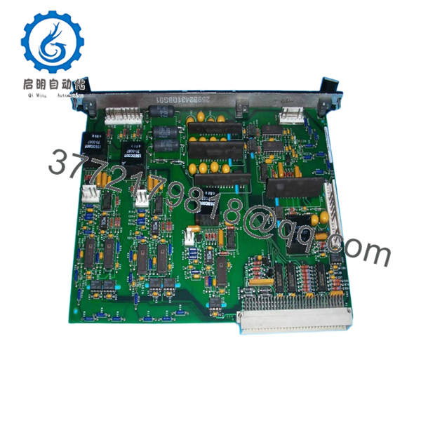
IS200SCNVG1ADC is an SCR-Diode Converter Interface Board used within GE Mark VI and Innovation Series drive systems. It functions as the control-to-bridge interface for stand-alone SCR-Diode converter assemblies and installs in Slot 6 of the Innovation rack architecture.
| Parameter | Value |
|---|---|
| Manufacturer | GE General Electric |
| Model | IS200SCNVG1ADC |
| Functional Acronym | SCNV |
| Product Type | SCR-Diode Converter Interface Board |
| Series | Mark VI / Innovation Series |
| Converter Support | 1,000 A and 1,800 A SCR-Diode converters |
| SCR Support | 6-pulse source driving 3 SCRs |
| Parallel SCR Support | Not supported |
| Gate Drive Circuits | 3 |
| Current Sense Circuits | 3 |
| Line-to-Line Voltage Feedback | 2 circuits |
| DC Link Feedback | 1 circuit |
| Dynamic Braking Gate Driver | 1 IGBT gate driver |
| Installation Location | Slot 6, Innovation rack |
| Backplane Interface | J15 on IS200CABP |
| Connector | 128-pin P1 |
| Weight | Approx. 10 oz |
| Warranty | Typically 12 months |
The board receives power through P1 and auxiliary transformer feeds. GE also integrated a serial memory device storing board identification and revision information accessible via the BRDID line.
4. Product Introduction
GE IS200SCNVG1ADC is an SCR-Diode Converter Interface Board used in GE Mark VI and Innovation Series turbine and drive systems. The board serves as the control-to-bridge interface between controller hardware and stand-alone SCR-Diode converter assemblies used in power conversion applications.
In field deployments, SCNV boards typically fail only after years of thermal cycling and cabinet contamination. When replacement time arrives, engineers usually insist on exact suffix matching because minor revision differences occasionally create startup issues that are invisible until gating logic becomes active.
5. Installation & Configuration Guide
Stage 1: Pre-Installation Preparation (Estimated: 10 minutes)
⚠️ Safety First: Notify operations of planned downtime. Verify drive and turbine systems are in a safe state. Apply lockout/tagout procedures. Wait at least 5 minutes for capacitor discharge.
Tools Required
- ESD wrist strap
- PH1 screwdriver
- Fluke 115 multimeter
- Wire labels
- Smartphone for photos
- ESD mat
- Flashlight
Data Backup
- Export controller and drive configuration.
- Record cabinet slot assignments.
- Photograph all field wiring.
- Photograph DIP and jumper settings.
- Record board revision details.
⚠️ Innovation and Mark VI cabinets frequently contain undocumented field modifications accumulated across outage cycles.
Stage 2: Removing the Old Module (Estimated: 5 minutes)
- Remove cabinet covers.
- Label every connector.
- Disconnect cables carefully.
- Release retention hardware.
- Pull board straight out.
Inspect:
- Backplane pins
- Connector wear
- Dust accumulation
- Heat discoloration
⚠️ Keep the old board available until commissioning finishes.
I’ve watched teams remove failed hardware immediately, then realize nobody documented jumper locations.
Stage 3: Installing the New Module (Estimated: 10 minutes)
- Wear grounded ESD protection.
- Verify exact model: IS200SCNVG1ADC
- Configuration Clone (Crucial): Replicate all jumper and switch settings exactly.
Pay attention to:
- SCR configuration
- Slot location
- Drive settings
- Interface assignments
This is the most common rookie mistake, but it happens constantly. Take a picture before you pull it. I can’t stress this enough.
- Insert board into Slot 6.
- Confirm connector engagement.
- Reattach all wiring.
Self-Checklist
- DIPs match
- Wiring secured
- Tabs locked
Stage 4: Power-On & Testing (Estimated: 10 minutes)
Pre-Power Check
Use a multimeter to verify no short exists on DC supply rails.
Power-up sequence:
- Energize rack only
- Observe startup LEDs and diagnostics
- Connect engineering workstation
- Verify board identification
- Check gate drive signals
- Perform dry-run signal testing
⚠️ Troubleshooting Note: If gating faults appear immediately, check firmware revision and slot assignment before replacing hardware again.
I saw a project lose almost two days because a replacement board revision changed internal behavior. The maintenance team kept replacing healthy hardware while the mismatch sat in front of them.
SOP Quality Transparency
Inbound Inspection & Traceability
- Verify OEM packaging and serial records.
- Perform anti-counterfeit inspections.
- Verify holographic labels.
- Inspect for scratches, corrosion, solder rework, and UV yellowing.
- Audit manuals and certificates.
Live Functional Testing
Testing performed using a GE-compatible Innovation rack where available.
Procedure:
- Power-on verification
- LED inspection
- Communication handshake checks
- Signal simulation
- Continuous operation exceeding 24 hours
- Thermal monitoring
Official Test Report generated after completion.
Electrical Parameter Testing
- 500 V Megger insulation resistance >10 MΩ
- Ground continuity verification
- Hipot testing where applicable
Firmware & Configuration Verification
- Document revision levels
- Photograph jumpers
- Record board configuration
Final QC & Packaging
- QC inspector signoff
- ESD anti-static packaging
- Bubble wrap protection
- Heavy-duty corrugated carton
- QC label with inspection date
Test photos and videos are available upon request.
Technical Pitfall & Survival Guide
❗ Firmware Revision Mismatch
Document board revision before removal.
I watched a replacement jump revision generations. The controller generated communication alarms for two days.
❗ DIP Switch / Jumper Errors
Take pictures first.
Simple mistake. Happens constantly.
❗ Terminal Wiring Assumptions
Even similar GE revisions occasionally change connector definitions.
Never wire from memory.
❗ Power Draw Calculations
Maintain at least a 20% power reserve.
Expanded cabinets consume power faster than engineers expect.
❗ ESD Damage
Wear a grounded wrist strap.
I once watched an engineer handle a replacement board during winter without grounding. Cabinet power came on and smoke followed immediately. Thousands of dollars gone in ten seconds.
Keep these checks in mind and you’ll save yourself 90% of typical rework time.

- IS200SCNVG1ADC
- IS200SCNVG1ADC
6. Frequently Asked Questions (FAQ)
Q1: Can I hot-swap this module?
No.
Do not hot-swap SCNV boards. Pulling interface hardware under power risks backplane damage and converter faults.
Q2: Is IS200SCNVG1ADC obsolete?
Yes.
This belongs to GE’s legacy Mark VI and Innovation Series hardware family. Current availability depends heavily on surplus inventory and tested industrial stock.
Q3: Is this genuinely new or refurbished?
Depends on source.
New Surplus generally means unused inventory from earlier projects. Refurbished hardware previously operated in service and later passed testing and inspection. Request photos and test reports.
Q4: What is the direct replacement if stock is unavailable?
Proceed carefully.
SCNV hardware revisions and suffixes matter. Match the exact IS200SCNVG1ADC suffix whenever possible. Verify compatibility before substitution.
Q5: Will replacing this board erase controller logic?
Normally no.
This board acts as an interface module and does not usually store application logic. Still, always create a backup before shutdown.
Q6: Why is surplus pricing lower than OEM pricing?
Inventory age.
Many suppliers purchased spare stock years ago and distribute remaining inventory today. Lower cost alone does not indicate lower quality.
Q7: Where does this board install inside the rack?
IS200SCNVG1ADC installs in Slot 6 of the Innovation Series rack and connects to J15 of the IS200CABP backplane assembly. Verify cabinet drawings before installation.


