
 WhatsApp: +86 16626708626
 Email:
  Phone: +86 16626708626
Description
Key Technical Specifications
| Parameter | Value |
|---|---|
| Manufacturer | GE |
| Model | IS200SCSAS1ADB |
| Product Family | Mark VI |
| Board Type | SCSI Adapter / Interface Board |
| Application | GE Mark VI turbine control |
| Primary Function | Internal system communication / SCSI interface |
| System Interface | Mark VI backplane |
| Communication | SCSI interface circuitry |
| Board Construction | Plug-in printed circuit board |
| Mounting | Mark VI control rack |
| PCB Identification | IS200SCSAS1ADB |
| PCB Revision | 1A |
| Functional Revision | DB |
| Status Indication | On-board status LEDs |
| Typical System | Gas turbine and steam turbine control systems |
| Installation Environment | Dedicated Mark VI control cabinet/rack |
Important specification note: Publicly available sources confirm the board’s Mark VI/SCSI function and backplane role, but I would not assign a specific input voltage, current consumption, SCSI transfer rate, or connector pinout without the GE hardware manual for this exact board revision. The IS200 designation identifies a PCB within the Mark VI architecture; it does not by itself establish a standalone power rating.
Product Introduction
The GE IS200SCSAS1ADB is a printed-circuit SCSI adapter/interface board for the GE Mark VI turbine control system. It provides the interface circuitry required for internal communication between control-system boards through the Mark VI backplane and is associated with GE gas and steam turbine control applications.
This is a system-specific PCB rather than a generic SCSI expansion card. Replacement decisions should therefore be based on the complete IS200SCSAS1ADB identification, board revision, connector arrangement, and existing Mark VI hardware configuration. Public inventory listings also identify this exact model as a GE SCSI adapter board.
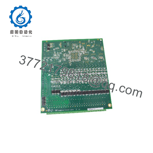
IS200SCSAS1ADB
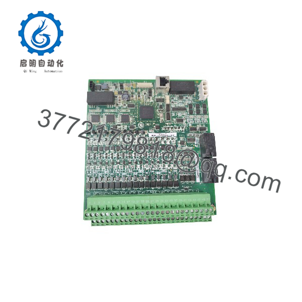
IS200SCSAS1ADB
Installation & Configuration Guide
Stage 1: Pre-Installation Preparation — Approximately 10 Minutes
⚠️ Safety First: The board belongs to a turbine control system. Coordinate the replacement with operations, place the turbine/control system in the approved maintenance state, apply lockout/tagout where required, and verify that the rack is de-energized before removing the PCB.
Tools Required
- ESD wrist strap
- Phillips screwdriver if required by the cabinet hardware
- Properly rated multimeter
- Wire/connector identification labels
- Smartphone or camera
- GE Mark VI hardware documentation
Data Backup
- Record the complete board identification.
- Photograph the installed board from several angles.
- Photograph every connector before removal.
- Record adjacent board positions and rack slot location.
- Record the existing Mark VI controller configuration.
- Compare the replacement board’s PCB markings with the removed unit.
⚠️ Do not rely on the model number alone when the board is being installed in a safety-critical turbine control cabinet. Revision markings and connector configuration should match the installed hardware.
Stage 2: Removing the Old Module — Approximately 5 Minutes
- Confirm the rack is de-energized.
- Establish ESD protection before touching the PCB.
- Remove any retaining hardware securing the board.
- Photograph the board and connector arrangement one final time.
- Disconnect applicable connectors carefully.
- Release the board from its rack/backplane position.
- Pull the PCB straight out rather than twisting it against the backplane connector.
- Inspect the backplane connector for bent contacts, contamination, or mechanical damage.
- Place the removed board in an ESD-safe bag.
⚠️ Keep the original board until the replacement has passed commissioning. It provides the fastest reference if the replacement exhibits unexpected behavior.
Stage 3: Installing the New Module — Approximately 5–10 Minutes
- Verify the exact part number: GE IS200SCSAS1ADB.
- Compare the PCB layout and connector arrangement with the original.
- Confirm the board revision markings.
- Put on the grounded ESD wrist strap.
- Align the PCB with the correct Mark VI rack slot.
- Insert the board straight into the backplane connector.
- Apply only the force necessary to seat the board correctly.
- Secure the retaining hardware.
- Reconnect each connector according to the photographs and GE wiring documentation.
- Inspect the board for loose connectors or improperly seated cables.
Self-Checklist
- IS200SCSAS1ADB identification verified
- PCB revision compared
- Correct Mark VI rack slot confirmed
- Backplane connector inspected
- SCSI connectors fully seated
- Retaining hardware secured
- ESD precautions maintained
- Original board retained for comparison
Stage 4: Power-On & Testing — Approximately 10–15 Minutes
- Perform a final visual inspection before applying power.
- Verify that no loose hardware or foreign material remains inside the rack.
- Restore power according to the approved Mark VI maintenance procedure.
- Observe the board’s status indicators.
- Check the Mark VI controller for hardware or communication faults.
- Verify communication between the affected control boards.
- Confirm that the turbine control application recognizes the expected hardware.
- Review diagnostic logs for new communication or rack faults.
- Perform the applicable control-system functional checks before returning the system to service.
- Record the replacement board’s identification and commissioning results.
⚠️ Do not interpret a normal LED indication as proof that the communication path is fully operational. Confirm the board through the Mark VI diagnostic environment and verify the affected control functions.
Frequently Asked Questions (FAQ)
1. What is the GE ?
The is a GE Mark VI SCSI adapter/interface board. It is used within the Mark VI turbine control architecture for communication and interface functions rather than as a general-purpose PLC I/O module.
2. Which GE system uses the ?
It belongs to the GE Mark VI turbine control system and is associated with gas and steam turbine control applications. It installs into the dedicated Mark VI control-rack architecture.
3. Is a standalone SCSI card?
No. Treating it as a generic computer SCSI adapter would be a mistake. Its electrical and mechanical interfaces are designed for the GE Mark VI control architecture, including its backplane and associated turbine-control boards.
4. Can I replace with another IS200 board?
Not simply because both boards begin with IS200. GE Mark VI IS200 boards perform different functions and have different electrical interfaces. A substitute should be verified against the exact GE part number, PCB revision, connector arrangement, and system documentation.
5. Does the require configuration after replacement?
The board itself is an interface PCB rather than a conventional PLC CPU containing the complete turbine application program. However, the Mark VI system configuration and hardware diagnostics still need to be checked after replacement. Do not assume that a physically identical board automatically eliminates the need for system verification.
6. Is obsolete?
The IS200 Mark VI hardware family is associated with GE’s legacy turbine-control platform, so procurement should be handled as a legacy/aftermarket spare-part requirement. However, “obsolete” should not be used to describe the exact commercial status of a particular inventory item without checking GE’s current documentation and availability.
7. How should I verify a replacement before purchasing?
Ask the supplier for clear photographs of the PCB nameplate, complete identification, revision markings, connectors, and actual unit. Also specify whether you require Factory Sealed, New Original/New Surplus, or Refurbished (tested) condition. For a turbine-control application, I would also request the supplier’s functional test documentation rather than accepting “tested” as an unsupported claim.



