
 WhatsApp: +86 16626708626
 Email:
  Phone: +86 16626708626
Description
3. Key Technical Specifications
| Parameter | Value |
|---|---|
| Manufacturer | General Electric (GE) |
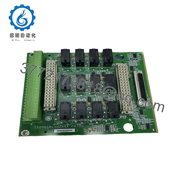
| Model Number | IS200SRLYH2AAA |
| Alternate Assembly | IS230SNRLH2A |
| Functional Acronym | SRLY |
| Product Type | Simplex Relay Output Terminal Board |
| Series | Mark VIe Speedtronic |
| Relay Channels | 12 Form-C relay outputs |
| Customer Terminals | 48 terminals |
| Compatible I/O Packs | IS220PDOA / YDOA |
| Max Load Voltage | 125 VDC |
| Relay Ratings | 24 VDC @ 5 A / 48 VDC @ 1.2 A / 125 VDC @ 0.6 A |
| Mounting Style | Cabinet-mounted S-type board |
| Communication Method | Isolated relay feedback contacts |
| Terminal Type | Euro-style pluggable terminals |
| Option Board Support | JW1 / JW2 connectors |
| Board Technology | Surface-mount |
| Hazardous Area Approval | Class I Div 2 / Zone 2 |
| Operating Temperature | -30 °C to +65 °C |
| Dimensions | Approx. 15.9 cm × 17.8 cm |
| Conformal Coating | Yes |
| Application | Turbine discrete output control |
| Condition Options | New Original, New Surplus, Refurbished (tested) |
The IS200SRLYH2AAA is designed for GE Mark VIe turbine control systems and provides relay-based discrete outputs for solenoids, alarms, contactors, and interposing relays in turbine and balance-of-plant applications.
4. Product Introduction
The GE IS200SRLYH2AAA is a Simplex Relay Output Terminal Board used in Mark VIe turbine control systems. It interfaces PDOA or YDOA I/O packs with external field devices through 12 Form-C relay outputs distributed across 48 customer terminals.
In field installations, this board is commonly used for controlling solenoids, annunciators, shutdown circuits, and auxiliary relay logic inside gas and steam turbine cabinets. Engineers typically choose this hardware when maintaining existing Mark VIe cabinets where wiring compatibility and relay isolation matter more than migrating to newer distributed I/O platforms.
5. Installation & Configuration Guide
Stage 1: Pre-Installation Preparation (Estimated Time: 10 Minutes)
⚠️ Safety First
- Notify operations and place the turbine or controlled process into a verified safe shutdown condition.
- Apply lock out/tag out procedures to all cabinet power sources.
- Wait at least 5 minutes for stored DC energy to discharge.
- Verify zero voltage with a multimeter before touching terminals.
Tools Required
- ESD wrist strap
- PH1 screwdriver
- Fluke 115 multimeter
- Wire labels
- Smartphone for documentation photos
- Torque screwdriver for terminal connections
Data Backup
- Export current Mark VIe configuration from ToolboxST.
- Record all output channel assignments.
- Photograph:
- Terminal wiring
- Shield grounding
- Relay output mapping
- Cabinet routing
- Document connected field devices before disconnecting wiring.
❗ Relay boards seem simple until someone mixes up output channels during a shutdown window. Then you’re tracing solenoid wiring at 2 AM with operations screaming for startup clearance.
Stage 2: Removing the Old Module (Estimated Time: 5 Minutes)
- Remove the cabinet protective cover.
- Label every terminal wire individually.
- Disconnect terminal blocks carefully. Do not pull wires directly.
- Remove mounting screws securing the board carrier.
- Pull the board assembly out evenly.
⚠️ Important
Do not force Euro-style terminal blocks sideways. I’ve seen terminal housings crack from rushed removal during outages.
- Inspect:
- Burn marks
- Loose terminal screws
- Corrosion
- Carbon tracking near relay contacts
⚠️ Keep the old module
Retain the original board until startup testing completes successfully.
Stage 3: Installing the New Module (Estimated Time: 10 Minutes)
- Wear a grounded ESD strap before handling the board.
- Verify:
- Exact model number
- H2AAA suffix
- Matching terminal layout
- Compatible I/O pack type
❗ Configuration Clone (Critical)
Even though the SRLY board itself has no configurable jumpers, wiring placement absolutely matters.
I’ve seen technicians shift a relay output by one terminal position and accidentally energize the wrong shutdown relay. That turns into a very long day fast.
- Mount the board securely onto the cabinet carrier.
- Insert terminal connectors carefully.
- Reconnect all field wiring using proper torque settings.
- Verify shield grounding locations match the original installation.
Self-Checklist
- Wiring labels verified
- Terminal screws tightened
- Grounding confirmed
- No pinched conductors
- Correct relay channel mapping
Stage 4: Power-On & Testing (Estimated Time: 15 Minutes)
Pre-Power Check
- Measure for shorts across the 24 VDC supply rail.
- Verify relay commons are correctly landed.
- Check cabinet grounding continuity.
Power-On Procedure
- Energize the control cabinet only.
- Observe associated I/O pack LEDs.
- Connect ToolboxST and verify:
- PDOA/YDOA recognition
- Output channel visibility
- No hardware faults
- Perform dry-run output testing.
- Confirm each relay energizes the intended field device.
⚠️ Troubleshooting Notes
Wiring Misalignment
This is one of the easiest mistakes to make during a rushed outage.
The SRLY uses dense terminal layouts, and one shifted wire can energize the wrong relay output. Always verify against the wiring diagram instead of relying on memory.
Relay Contact Ratings
Do not exceed relay current limits.
At 24 VDC, the relay supports higher current loads. At 125 VDC, current capacity drops significantly. I’ve seen field relays welded shut because someone assumed all voltage ranges carried the same amp rating.
Power Supply Loading
Multiple relay outputs energizing simultaneously can increase cabinet load unexpectedly.
Always verify:
- Total 24 VDC supply margin
- Interposing relay current draw
- Solenoid startup current
Leave at least 20% supply headroom.
ESD Handling
❗ Use ESD protection every time.
I once watched a contractor handle a spare relay board straight from a cardboard box during winter maintenance. Static discharge damaged two output channels before installation even finished.
Keep these checks in mind and you’ll save yourself 90% of typical rework time.

- IS200SRLYH2AAA
- IS200SRLYH2AAA
6. Frequently Asked Questions (FAQ)
Q1: Can the IS200SRLYH2AAA be hot-swapped?
No.
This terminal board is not intended for live insertion or removal. Removing the board under power can damage the I/O pack, trip turbine outputs, or create unintended relay state changes.
Always isolate cabinet power before replacement.
Q2: Is the IS200SRLYH2AAA obsolete?
Yes.
The Mark VIe platform remains active in many turbine facilities, but some hardware revisions are now sourced mainly through surplus inventory and specialized industrial automation suppliers. Stock availability changes frequently during outage seasons.
Q3: What devices does this board typically control?
Typical applications include:
- Solenoids
- Alarm horns
- Shutdown relays
- Contactor coils
- Auxiliary turbine permissives
- Interposing relays
In real plants, these boards often sit right in the middle of critical trip logic chains, so wiring accuracy matters.
Q4: Does this board store application logic?
No.
The IS200SRLYH2AAA functions as a relay output terminal board. Application logic normally resides inside the Mark VIe controller and associated processors.
Still, always back up the system before maintenance work.
Q5: What is the most common installation mistake?
Miswired output channels.
Honestly, this happens constantly during turnaround outages. Someone moves one terminal over, and suddenly the wrong solenoid energizes during testing.
Take photos before removal and verify every output point manually.
Q6: Is this board compatible with both PDOA and YDOA I/O packs?
Yes.
The SRLY terminal board is designed to interface with compatible GE PDOA and YDOA output packs used in Mark VIe architectures. Verify exact hardware revision compatibility before installation.
Q7: What testing should be completed before shipment?
A proper industrial QC process should include:
- OEM traceability inspection
- Serial number verification
- Visual inspection for corrosion, rework, or damaged terminals
- Relay continuity testing
- Output activation testing using a compatible GE rack
- Insulation resistance testing with a 500 V Megger
- 24-hour burn-in testing
- ESD-safe packaging and final QC sign-off
Verified fully functional under load testing. Test reports and startup videos should be available upon request.


