
 WhatsApp: +86 16626708626
 Email:
  Phone: +86 16626708626
Description
3. Key Technical Specifications
| Parameter | Value |
| Manufacturer | General Electric (GE) |
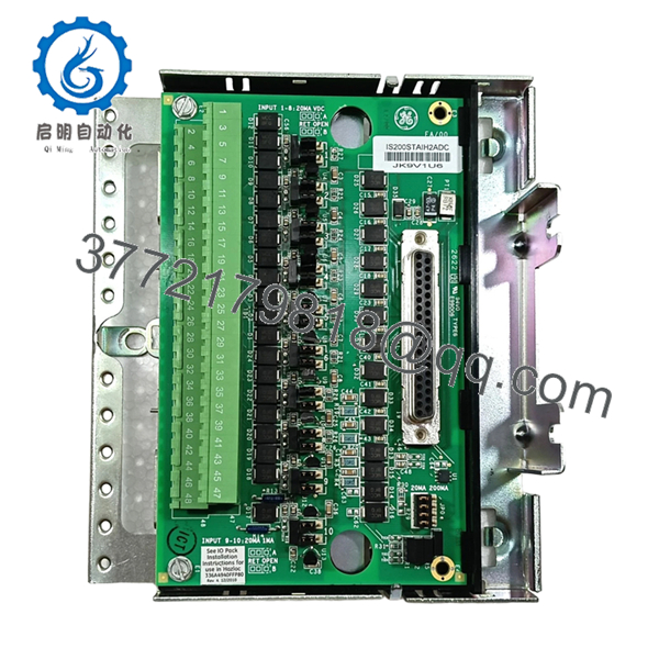
| Part Number | IS200STAIH2ADC |
| Control System Series | Speedtronic Mark VI |
| Board Functional Acronym | STAI (Simplex Analog Input Terminal Board) |
| Group Variation | Group 2 (H2 Variant – Simplex configuration with Euro-style/Barrier block profile) |
| Hardware Revision | ADC (Designates specific structural revision and component footprint) |
| Analog Input Channels | 10 differential or single-ended points (supports \pm10 V, 4-20 mA) |
| Analog Output Channels | 2 operational outputs for analog control loops |
| Surge Protection | Integrated metal oxide varistors (MOVs) and high-frequency filtering |
| Interface Connections | Dual 37-pin D-sub connectors (labeled JR1 and JS1) |
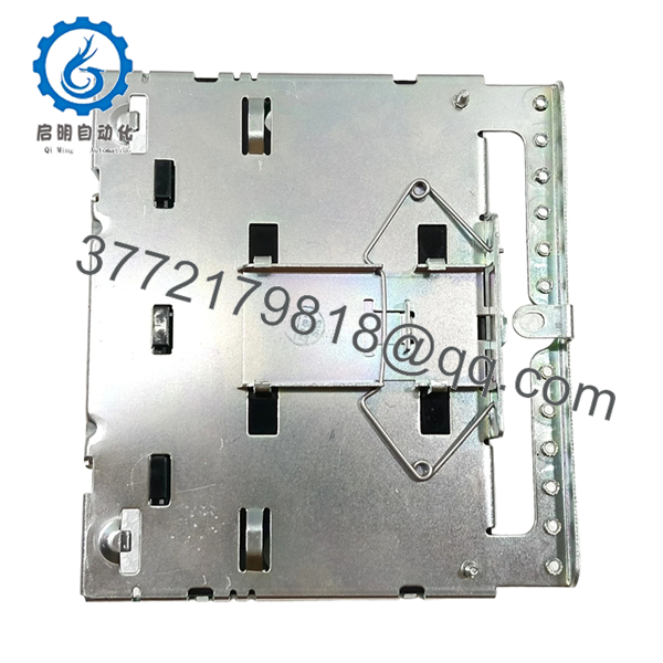
| Form Factor | DIN-rail or circuit board rack mounted terminal card |
| Weight | 1.80 lbs (0.82 kg) |
4. Product Introduction & Supply Chain Strategy
The GE IS200STAIH2ADC is a Simplex Analog Input Terminal Board designed for General Electric’s legacy Mark VI Speedtronic turbine control platforms. This board serves as the primary, high-density physical termination interface for field wiring, accepting up to 10 analog inputs and providing 2 analog outputs. It accommodates standard transducer loops, such as \pm10 V and 4-20 mA signals, and features integrated noise-suppression networks and metal oxide varistors (MOVs) to protect upstream VME processing cards (like the VAIC board) from field-induced electrical surges.
From a supply chain perspective, stocking the IS200STAIH2ADC as a New Surplus asset is an essential method for optimizing plant reliability metrics. Because the Mark VI automation lineup is obsolete, sourcing critical termination components during an emergency outage introduces severe lead time variability. Choosing a certified New Surplus module eliminates the reliability risks associated with unverified refurbished components, which often suffer from hidden stress cracks in the terminal traces or degraded surge-suppression circuits due to past field faults. Maintaining a zero-hour backup card directly on-site reduces the Total Cost of Ownership (TCO) and prevents localized I/O termination faults from causing extended, costly plant shutdowns.
- IS200STAIH2ADC
- IS200STAIH2ADC
5. Installation & Configuration Guide
Stage 1: Pre-Installation (Prep & Safety)
- Safely de-energize all power lines leading to the target Mark VI terminal cabinet by executing full plant lock-out/tag-out (LOTO) protocols.
- Put on a grounded static-dissipative wrist strap and ensure it is connected to an unpainted metal section of the control enclosure frame.
- Use a high-resolution camera to document all terminal block field wiring positions, wire tags, and the routing of the 37-pin D-sub cables.
Stage 2: Removal
- Systematically disconnect the field wires from the terminal blocks using a properly sized terminal screwdriver, checking that all wire markers remain clear and intact.
- Unplug the heavy-duty 37-pin D-sub ribbon cables from the JR1 and JS1 ports on the board.
- Release the card from its DIN-rail mounting clips or backplate screws, and remove the card straight out without twisting or catching adjacent assemblies.
Stage 3: Installation (Clone & Seat)
- Place the old terminal card and your New Surplus IS200STAIH2ADC module side-by-side on an ESD-safe workspace mat.
- Verify that any hardware jumpers on the new board match the original configuration precisely to ensure proper signal conditioning (e.g., configuring channels for voltage vs. current loop modes).
- Snap the new board firmly onto the DIN rail or secure it to the backplate screws, then plug the JR1 and JS1 D-sub cables back into their respective headers.
Stage 4: Power-On & Testing
- Re-terminate all field wiring into the barrier terminal blocks according to your pre-installation reference photos and wiring diagrams.
- Restore system control power and check for any localized overheating or burning smells near the terminal blocks.
- Access the master controller diagnostics via the HMI to verify that all 10 analog input channels are reading stable, calibrated field telemetry and that no open-circuit or ground faults are reported on the loop.
6. Firmware/Software Versions & Upgrade Notes
The IS200STAIH2ADC acts as a passive-to-active physical signal routing and conditioning interface, meaning it does not contain a programmable microprocessor or flash firmware kernel. The “H2ADC” suffix indicates its classification as a Group 2 simplex hardware configuration with specific physical trace updates.
While the card does not require field firmware flashes, you must verify that the I/O configuration files within your Toolbox or ToolboxST software match the specific hardware revision group. Swapping a Group 1 terminal board for this Group 2 variant without modifying the system’s hardware definition files can cause channel assignment mismatches, incorrect sensor scaling values, or diagnostic errors on the paired VME processing modules.
7. Frequently Asked Questions (FAQ)
Q: What is the main difference between your New Surplus STAI cards and refurbished ones?
A: This product is a Brand New Surplus unit. It is not used, not pulled from a decommissioned plant, and not refurbished. Refurbished terminal boards are typically cleaned after being removed from service, meaning their onboard resistors and surge-protection varistors have already experienced thousands of hours of thermal loading and field exposure. Our New Surplus units have zero runtime wear, ensuring long-term signal integrity and component longevity.
Q: Can we perform a hot-swap on this terminal board while the turbine is online?
A: No. Replacing an I/O terminal board like the IS200STAIH2ADC while the system is energized is highly discouraged. Disconnecting field wiring or the master D-sub cables while online will break the active control loop, instantly causing signal drops that can trigger an emergency turbine trip or damage connected field instrumentation.
Q: What do the JR1 and JS1 connectors on this board do?
A: The JR1 and JS1 connectors are high-density 37-pin D-sub ports. They host the shielded cables that transmit the conditioned analog field signals from the STAI terminal block directly back to the VAIC input cards located in the main VME control rack.
Q: Does this board support both 4-20 mA and voltage inputs at the same time?
A: Yes. The IS200STAIH2ADC can handle a combination of voltage and current inputs across its 10 channels. However, you must position the onboard hardware jumpers correctly for each channel to enable the proper burden resistor for 4-20 mA current loops or bypass it for voltage inputs.
Q: Why does a New Surplus terminal card carry a higher price tag than refurbished versions?
A: Our pricing reflects the strategic market value of providing uncompromised, zero-hour legacy stock. Refurbished terminal cards often have micro-fractures in the screw terminals or degraded varistors that fail under field surge conditions. A certified New Surplus card eliminates those unpredictable failure points, protecting your facility against thousands of dollars in lost generation.
Q: What is the standard warranty period for this item?
A: We provide a full 1-year functional warranty on this New Surplus board, matching the protection period of an active OEM component to give your maintenance team complete peace of mind.


