
 WhatsApp: +86 16626708626
 Email:
  Phone: +86 16626708626
Description
3. Key Technical Specifications
| Parameter | Value |
| Functional Acronym | TBCI (Contact Input with Group Isolation) |
| Compatible Systems | GE Speedtronic Mark VI and Mark VIe Series |
| Number of Channels | 24 discrete dry contact inputs |
| Input Filter Configuration | Onboard RC filters (approx. 4 ms hardware response) |
| Excitation Voltage | Nominal 24 VDC (floating range 16 to 32 VDC) |
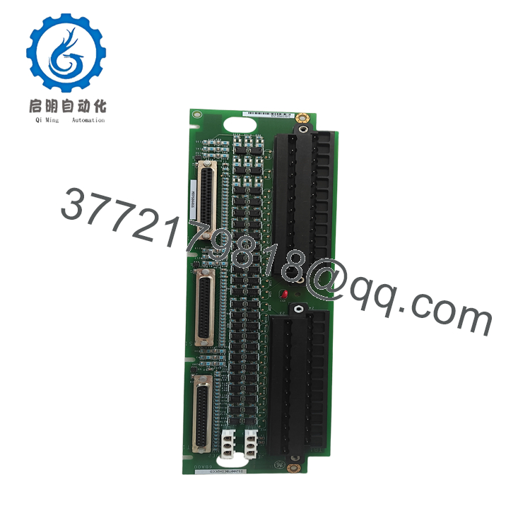
| Barrier Terminal Blocks | 2 x High-durability removable terminal strips (TB1 & TB2) |
| Maximum Conductor Size | Accepts up to #12 AWG wires |
| VME/IO Cabling Ports | 3 x DC-37 female connectors (JR1 for Simplex; JR1, JS1, JT1 for TMR) |
| Power Distribution Inputs | Plugs JE1 and JE2 for excitation supply |
| Onboard Protection | Integrated surge and high-frequency noise suppression networks |
| Hardware Settings | None (Fully configured via software/firmware) |
4. Product Introduction & Supply Chain Strategy
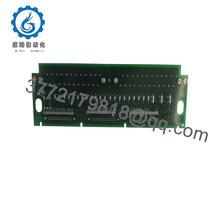
The GE Vernova IS200TBCIH2CCD is a high-density Contact Input with Group Isolation (TBCI) terminal board designed for GE’s Speedtronic Mark VI and Mark VIe turbine control architectures. Serving as the primary physical landing point for field signals, this card handles up to 24 dry contact inputs. The board uses group isolation and integrated noise suppression networks on every circuit to shield the control core from severe electrical transients, high-frequency spikes, and field surges common in heavy power generation plants.
For plant management and maintenance teams, the IS200TBCIH2CCD is a vital “First-Line” component. Since terminal boards interface directly with harsh field environments, they are vulnerable to external power surges, corrosive dust buildup, and terminal screw strip-outs. If a contact input fails, it can blind the turbine control system to critical safety interlocks, triggering immediate emergency trips.
Selecting a certified New Surplus terminal board over a refurbished or repaired option is a critical safety choice. Refurbished terminal cards often have degraded optocouplers, micro-fractures near high-current traces, and high contact resistance on the connectors. Storing 1–2 zero-hour original surplus TBCI cards ensures immediate, reliable replacements, helping you avoid costly downtime.

- IS200TBCIH2CCD
- IS200TBCIH2CCD
5. Installation & Hardware Configuration
Stage 1: Pre-Installation Prep
Safely isolate and lock out all 24 VDC external excitation power lines leading to the target control cabinet. Disconnect the rack power feeding the associated I/O processor pack. Fasten a grounded ESD wrist strap to your arm and connect its clamp to an unpainted section of the steel cabinet enclosure. Before removing the existing board, document the landing wire layout for all 24 channels.
Stage 2: Mechanical Extraction
Unscrew and unplug the two removable barrier terminal blocks (TB1 and TB2) from the face of the IS200TBCIH2CCD, keeping the field wiring intact. Unplug the DC-37 system cables connected to the JR1, JS1, and JT1 communication jacks. Unscrew the mounting fasteners located at the corners of the card chassis, then carefully slide the board out of its cabinet standoffs.
Stage 3: Board Mounting & Connections
Verify that the replacement IS200TBCIH2CCD has clean, unbent pins inside all three DC-37 female connectors. Mount the card securely onto its cabinet standoffs, ensuring the conductive grounding rings around the mounting screws are tight to maintain low-impedance bonding to the chassis. Replug the DC-37 cables according to your system’s architecture:
- Simplex Systems: Connect the I/O processor cable strictly to port JR1.
- Triple Modular Redundant (TMR) Systems: Connect cables to ports JR1, JS1, and JT1 to establish redundant voter communication loops.
Stage 4: Wiring & Commissioning
Re-seat the wired barrier terminal blocks (TB1 and TB2) and tighten their retaining screws. Plug in the excitation power sources at connectors JE1 and JE2. Restore auxiliary and system power. Monitor the status indicators on the connected I/O processor pack; the diagnostic logs within your ToolboxST or ControlSystem Toolbox software must show clean communication, clear excitation voltage, and active contact signal transition mapping.
6. System Diagnostics & Operational Tests
The IS200TBCIH2CCD relies on its connected I/O pack to run automated diagnostics and monitor loop integrity:
- Excitation Voltage Monitoring: The connected I/O module constantly measures the contact excitation voltage. If this level drops below 40% of nominal parameters (typically below 9.6 VDC), the system triggers a diagnostic alarm to alert operators of a power drop.
- Failsafe Contact Diagnostics: During normal operation, the control system regularly tests the optocouplers by pulsing the internal thresholds high and low. If an input channel fails to respond during this brief diagnostic cycle, the system forces that point into a failsafe “open contact” state and flags an I/O fault.
- TMR Disagreement Vetoing: In a TMR system, the controller continuously votes on the 24 inputs across the three redundant channels. If one channel’s reading disagrees with the other two, the system logs a voting mismatch fault, identifying the specific channel for physical wiring or terminal verification.
7. Frequently Asked Questions (FAQ)
What is the role of the “H2CCD” suffix on this model number?
The suffix indicates the specific manufacturing revision and component configuration group. The H2C specifies the physical board revision, while the CD suffix denotes its component layout group. This specific combination is designed for standard dry contact applications on Mark VI platforms and is backward-compatible with older H2C systems.
Is this board a refurbished unit?
No. This is a Brand New Surplus unit. It has not been used, has not been pulled from a decommissioned power plant, and has not undergone third-party repairs. The module ships in its original protective anti-static packaging, featuring clean, factory-applied solder tracks and pristine, unserrated connector terminals.
Why does this module feature two separate power connection points (JE1 and JE2)?
The dual power plugs, JE1 and JE2, allow you to wire redundant external 24 VDC power supplies to the board. This configuration ensures that if one excitation supply fails, the second line instantly maintains the contact loop voltage, preventing field loop loss or diagnostic trips.
Can I plug in or remove the field terminal blocks while the excitation circuit is live?
While the removable terminal blocks are designed for easy maintenance, pulling them under load can generate high-voltage inductive arcs if you are running large external relay loops. Always de-energize the excitation circuit before unplugging the TB1 and TB2 blocks to protect yourself and prevent damage to the onboard surge suppression circuits.
What warranty terms cover this legacy terminal board?
We protect this New Surplus IS200TBCIH2CCD board with a comprehensive 1-year operational warranty from your date of purchase. If a component defect occurs during this window, we handle replacement or repair immediately, shielding your operating budget from the limited 30-day structural warranties typically packaged with refurbished alternative components.



