
 WhatsApp: +86 16626708626
 Email:
 Phone: +86 16626708626
Description
Core Product Summary
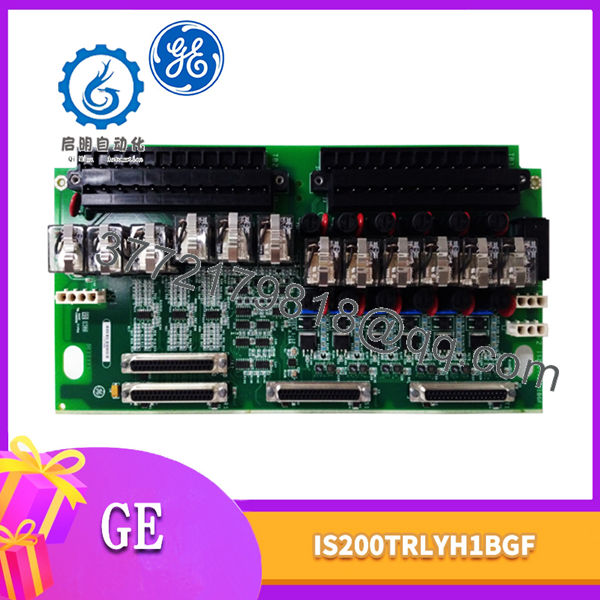
The GE IS200TRLYH1BGF is a Relay Output with Coil Sensing (TRLYH1B) terminal board for the GE Mark VI Turbine Control System. It provides 12 plug-in magnetic relays that convert controller commands into relay-contact outputs for field devices.
The board includes six relay circuits that can be jumper-configured as dry Form-C contact outputs or used to drive external solenoids. It also provides five unpowered isolated Form-C contact relays and one isolated Form-C contact for special applications such as ignition transformers. Relay operation and coil-current diagnostics are performed at the frame rate, with two consecutive disagreements latching an alarm.
Key Technical Specifications
| Parameter | Verified information |
|---|---|
| Manufacturer | General Electric (GE) |
| Exact model | IS200TRLYH1BGF |
| Functional designation | TRLYH1B, Relay Output with Coil Sensing |
| System family | GE Mark VI Turbine Control System |
| Product type | Relay output terminal board |
| Relay channels | 12 plug-in magnetic relays |
| Configurable outputs | Relays 1 through 6, configurable as dry Form-C contacts or solenoid drivers |
| Isolated contact outputs | Relays 7 through 11, unpowered isolated Form-C contacts |
| Special-purpose output | Output 12, isolated Form-C contact for applications such as ignition transformers |
| Field terminals | Two I/O terminal blocks, 24 terminals each |
| Wire capacity | Up to #12 AWG |
| Relay load current | 0.6 A at 125 VDC; 3.0 A at 24 VDC or 115/230 VAC |
| Relay response time | 25 ms maximum on and off; relays driven at frame rate |
| Contact voltage rating | 500 VAC contact-to-contact for one minute |
| Coil-to-contact isolation | 1,500 VAC for one minute |
| Diagnostics | Relay contact voltage monitoring; coil current versus command at frame rate; solenoid excitation voltage monitoring |
| Configuration | Jumpers JP1 through JP12; contact-voltage sensing selected by jumpers |
| Protection devices | Fuses FU1 through FU12 |
| Board dimensions | 17.8 cm wide × 33.02 cm high |
| Operating temperature | -30 to +65 °C |
| Reference documentation | GEH-6421, Mark VI Turbine Control System Guide |
Engineering Selection Highlights
- Mark VI relay-output role: The IS200TRLYH1BGF is a TRLYH1B relay output terminal board, so it is selected where Mark VI controller commands must operate field relays or solenoids.
- Twelve relay channels: Its 12 plug-in magnetic relays provide the output capacity for relay-based field interfaces within a Mark VI control cabinet.
- Configurable first six outputs: Relays 1 through 6 can be configured by jumpers as dry Form-C contacts or solenoid drivers, allowing the board to match different field-device requirements.
- Solenoid-power dependency: Solenoid power for outputs 1 through 6 connects at JF1; JF2 can daisy-chain power to other TRLY boards, while output 12 uses connector JG1.
- Coil-sensing diagnostics: The board compares relay-coil current with the commanded state at the frame rate; two consecutive disagreements latch an alarm.
- Terminal-block capacity: The two 24-terminal blocks accept wire up to #12 AWG and provide the field-side connection points for the 12 relay outputs.
- Mark VI control connection: In simplex operation, connector JA1 links the TRLY board to the I/O processor; in triple-modular-redundant (TMR) operation, connectors JR1, JS1, and JT1 are used.
IS200TRLYH1BGF
IS200TRLYH1BGF
System Compatibility & Integration Requirements
| Item / Dependency | Verified Compatibility or Requirement | Practical Note |
|---|---|---|
| Control platform | GE Mark VI Turbine Control System | The IS200TRLYH1BGF is a Mark VI TRLYH1B relay output terminal board. |
| Controlling boards | VCCC, VCRC, or VGEN | The TRLY board is under the control of one of these Mark VI boards. |
| Simplex connection | Connector JA1 | Used for control signals and monitor feedback voltages between the I/O processor and TRLY. |
| TMR connection | Connectors JR1, JS1, and JT1 | Used in triple-modular-redundant Mark VI configurations. |
| Relay outputs | 12 plug-in magnetic relays | Relays 1 through 6 are configurable; relays 7 through 11 are dry isolated contacts; output 12 is a special isolated Form-C contact. |
| Solenoid power | JF1 for outputs 1 through 6; JG1 for output 12 | JF2 can daisy-chain power to other TRLY boards. |
| Field wiring | Two 24-terminal blocks; up to #12 AWG | Relay-output wires connect directly to the terminal blocks. |
| Configuration | Jumpers JP1 through JP12 | Used for relay configuration and contact-voltage sensing selection. |
| Protection | Fuses FU1 through FU12 | Provide individual relay-related protection. |
| Firmware/software context | Mark VI control system | Relay operation and diagnostics occur at the control-system frame rate. |
Dimensions, Mounting & Connection Notes
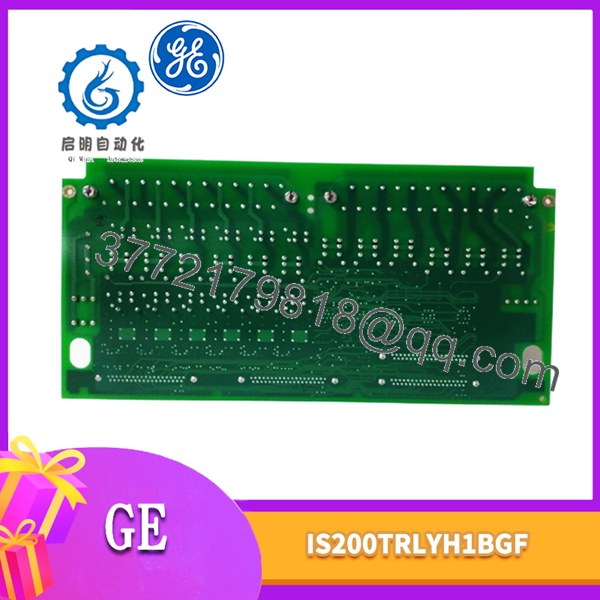
The IS200TRLYH1BGF measures 17.8 cm wide by 33.02 cm high. It is a Mark VI terminal board installed in the turbine-control cabinet and connected to the Mark VI I/O architecture through molded-plug cables.
The board provides two I/O terminal blocks, each with 24 terminals, for direct connection of the 12 relay-output wires. The terminal blocks accept wire up to #12 AWG. Cable shields terminate at the chassis shield strips located beside each terminal block.
Solenoid power for outputs 1 through 6 connects at JF1. JF2 can be used to daisy-chain power to other TRLY boards, or power can be wired directly to TB3 when JF1 and JF2 are not used. Power for the special solenoid output, output 12, connects at JG1.
Detailed Product Overview
The GE IS200TRLYH1BGF is a Relay Output with Coil Sensing (TRLYH1B) terminal board for the GE Mark VI Turbine Control System. It holds 12 plug-in magnetic relays and provides the relay-output interface through which Mark VI controller commands operate field devices.
The board’s output structure is divided by function. Relays 1 through 6 are configurable by jumpers as either dry Form-C contact outputs or solenoid drivers. Relays 7 through 11 provide unpowered isolated Form-C contacts. Output 12 is an isolated Form-C contact intended for special applications, including ignition transformers.
For solenoid operation, the board supports a standard 125 VDC or 115/230 VAC source, or an optional 24 VDC source with individual jumper-selectable fuses and on-board suppression. Solenoid power for outputs 1 through 6 connects at JF1, while JF2 can daisy-chain power to other TRLY boards. When JF1 and JF2 are not used, power can be wired directly to TB3. Output 12 receives its solenoid power through connector JG1.
The relay outputs connect directly to two I/O terminal blocks on the board. Each block has 24 terminals and accepts wire up to #12 AWG. Cable shields terminate at the chassis shield strips located beside each terminal block. The board’s physical size is 17.8 cm wide by 33.02 cm high.
Relay performance is defined by the board’s operating characteristics. The relays are driven at the frame rate and have a maximum on and off response time of 25 ms. The documented load-current ratings are 0.6 A at 125 VDC and 3.0 A at 24 VDC or 115/230 VAC. Contact-to-contact voltage is rated at 500 VAC for one minute, while coil-to-contact voltage is rated at 1,500 VAC for one minute.
Diagnostics are an integral part of the TRLYH1B function. The board monitors relay contact voltage and compares relay-coil current with the commanded state at the frame rate. Two consecutive disagreements latch an alarm. Solenoid excitation voltage is also monitored downstream of the fuses. Diagnostic results are reported through the composite diagnostic signal L3DIAG_xxxx, with ID-chip mismatch also monitored and alarms latched and reset through RESET_DIA.
Configuration is performed through jumpers JP1 through JP12. If contact-voltage sensing is required for selected relays, the corresponding jumpers are inserted. Fuses FU1 through FU12 provide the board’s relay-related protection.
In a Mark VI system, the TRLY board is under the control of either the VCCC, VCRC, or VGEN board and supports both simplex and TMR configurations. In simplex operation, connector JA1 transmits control signals and monitor feedback voltages between the I/O processor and the TRLY board. In TMR operation, connectors JR1, JS1, and JT1 are used.
Applications & System Role
Within a GE Mark VI Turbine Control System, the IS200TRLYH1BGF serves as the relay-output interface between controller commands and field devices. Its 12 relays convert control-system commands into contact outputs that can operate relays, solenoids, and other field-connected devices.
The first six relay circuits provide configurable dry-contact or solenoid-drive capability. The next five relays provide unpowered isolated Form-C contacts, while output 12 provides an isolated Form-C contact for special applications such as ignition transformers. This output structure makes the board relevant to Mark VI applications requiring relay-based actuation and isolation between the control system and field devices.
FAQ
What is the GE IS200TRLYH1BGF?
It is a GE Mark VI Relay Output with Coil Sensing (TRLYH1B) terminal board that provides 12 plug-in magnetic relays for field-device control.
How many relay outputs does the IS200TRLYH1BGF provide?
It provides 12 relay outputs: six configurable relays, five dry isolated Form-C relays, and one special isolated Form-C output.
Which relays can drive solenoids?
Relays 1 through 6 can be jumper-configured as dry Form-C contact outputs or solenoid drivers.
What is the purpose of output 12?
Output 12 is an isolated Form-C contact intended for special applications such as ignition transformers.
What wire size does the terminal block accept?
Each of the two 24-terminal blocks accepts wire up to #12 AWG.
What are the relay load-current ratings?
The relays are rated for 0.6 A at 125 VDC and 3.0 A at 24 VDC or 115/230 VAC.
How does the coil-sensing diagnostic work?
The board compares relay-coil current with the commanded state at the frame rate; two consecutive disagreements latch an alarm.
Which Mark VI boards control the TRLY board?
The TRLY board is under the control of the VCCC, VCRC, or VGEN board, depending on the Mark VI configuration.



