
 WhatsApp: +86 16626708626
 Email:
  Phone: +86 16626708626
Description
3. Key Technical Specifications
| Parameter | Value |
|---|---|
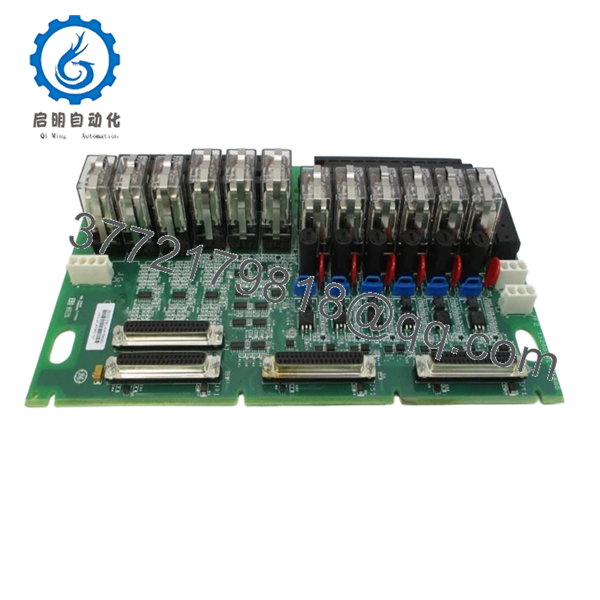
| System Compatibility | GE Mark VI / Mark VIe |
| Module Type | Termination Relay Board |
| Relay Configuration | 12 plug-in relays (3 groups of 4) |
| Output Type | Form-C dry contact / solenoid drive |
| Control Voltage | 24 / 48 / 125 V DC |
| Response Time | 25 ms ON / OFF (typical) |
| Max Inrush Current | 10 A |
| Contact Material | Silver cadmium oxide |
| Noise Suppression | MOV-based suppression |
| Mounting | Panel / DIN rail (application dependent) |
| Operating Temperature | −30 to +65°C |
| Storage Temperature | −40 to +85°C |
| Lifecycle Status | Mature platform – lifecycle monitoring required |
4. Product Introduction & Supply Chain Strategy
The GE IS200TRLYH1BGG is a termination relay board used in Mark VI turbine control systems to interface control logic with field devices. It manages relay outputs, solenoid actuation, and coil sensing, providing reliable switching and signal isolation between control processors and external equipment.
From an inventory strategy standpoint, this module sits in a high-criticality / moderate consumption category. While not fully obsolete, supply channels are tightening. A structured buffer stock strategy (Min 1 / Max 2 per unit) mitigates lead time variability. New Surplus sourcing eliminates relay fatigue risks common in refurbished units, improving Total Cost of Ownership (TCO) and reducing unplanned outages.

- IS200TRLYH1BGG
5. Installation & Configuration Guide
Stage 1: Pre-Installation (Prep & Safety)
- Execute full lock-out/tag-out (LOTO).
- Wear ESD wrist strap; use insulated tools.
- Document all terminal wiring and relay assignments.
- Verify voltage class (DC vs AC configuration).
Stage 2: Removal
- Label and disconnect field wiring from terminal blocks.
- Loosen mounting hardware.
- Remove module without stressing terminal connectors.
Stage 3: Installation (Clone & Seat)
- Install new board and secure mounting points.
- Reconnect wiring exactly per original terminal mapping.
- Verify relay grouping (3×4 structure).
- Confirm correct voltage supply selection.
Stage 4: Power-On & Testing
- Reapply control power and monitor for abnormal current.
- Trigger test outputs and confirm relay actuation.
- Validate coil sensing feedback and alarm conditions.
- Check system diagnostics for communication or output faults.
6. Firmware/Software Versions & Upgrade Notes
- Firmware Dependency: Controlled at system level (Mark VI controller), not on-board.
- Compatibility Note: Relay timing is logic-driven—controller firmware mismatches can affect actuation timing.
- Upgrade Risk: Changing controller firmware during board replacement can introduce sequencing faults.
- Best Practice: Maintain identical control firmware and validate I/O mapping before energizing outputs.
7. Frequently Asked Questions (FAQ)
Q1: Is this unit truly new or surplus stock?
This product is a Brand New Surplus unit. It is not used, not pulled from a decommissioned plant, and not refurbished. It retains original OEM build integrity with zero relay wear.
Q2: Why avoid refurbished relay boards?
Relays have mechanical life limits. Refurbished boards often reuse aged relays with unknown cycle counts. A single relay failure can trip turbine auxiliaries or protection circuits.
Q3: Is this considered a critical spare?
Yes—A/B class depending on plant redundancy. Loss of relay output capability directly impacts turbine control and interlocks.
Q4: What stocking policy do you recommend?
- Min: 1 unit per turbine system
- Max: 2 units (based on failure rate and lead time variability)
- Strategy: Buffer stock + vendor consolidation + cross-site sharing
Q5: Can this module be hot-swapped?
No. Relay boards interface directly with field circuits. Always power down to avoid arcing or false actuation.
Q6: Does the module require programming?
No onboard programming. Configuration is defined by wiring and control logic. However, incorrect wiring replication is a common failure point.
Q7: What lifecycle risks should be considered?
This is a mature platform. Monitor OEM discontinuation signals and prepare a last-time-buy strategy before global inventory tightens further.


