
 WhatsApp: +86 16626708626
 Email:
  Phone: +86 16626708626
Description
3. Key Technical Specifications
| Parameter | Value |
|---|---|
| Part Number | IS200TTURH1B |
| Manufacturer | General Electric |
| Product Type | Turbine Protection Input Terminal Board |
| Functional Acronym | TTUR |
| Series | Speedtronic Mark VI |
| Primary Function | Turbine overspeed and synchronization interface |
| Number of Inputs | 12 passive pulse-rate inputs |
| MPU Pulse Rate Range | 2 Hz to 20 kHz |
| MPU Accuracy | 0.05% of reading |
| MPU Sensitivity | 27 mV peak |
| Breaker Coil Output | 5 A at 125 V DC |
| Shaft Voltage Signal | ±5 V DC pulse monitoring |
| Shaft Voltage Wiring Distance | Up to 300 m |
| Relay Configuration | K25, K25P, K25A permissive relays |
| Supported Architectures | Simplex and TMR |
| Wiring Capacity | Accepts up to #12 AWG conductors |
| Connector Types | Terminal blocks, JR/JS/JT signal connectors |
| Operating Temperature | −30 °C to +65 °C |
| Mounting Style | Mark VI terminal board mounting |
| Cooling Method | Passive cabinet airflow |
| Condition Options | New Surplus / Refurbished Tested |
| Availability | Limited surplus inventory globally |
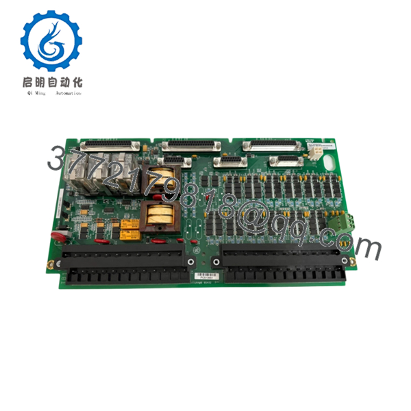
Technical references identify the IS200TTURH1B as a Primary Turbine Protection Input terminal board used in GE Mark VI turbine control systems for overspeed protection, synchronization, and breaker permissive control.
4. Product Introduction
The GE IS200TTURH1B is a Turbine Protection Input Terminal Board designed for GE Speedtronic Mark VI turbine control systems. The board interfaces magnetic pickup speed sensors, shaft voltage monitoring circuits, generator synchronization signals, and breaker permissive logic within turbine protection architectures.
In field service work, TTUR boards usually become critical during startup troubleshooting because they sit directly between turbine speed sensing hardware and the VTUR control processor. A noisy MPU input, failed relay, or grounding issue on this board can create nuisance overspeed trips or failed synchronization attempts that are difficult to diagnose under outage pressure.
- IS200TTURH1B
- IS200TTURH1B
5. Installation & Configuration Guide
Stage 1: Pre-Installation Preparation (Estimated Time: 10 Minutes)
⚠️ Safety First
- Notify operations and place the turbine in a verified shutdown state.
- Lock out and tag out all control cabinet and breaker power sources.
- Wait at least 5 minutes for capacitor discharge and verify absence of voltage with a meter.
❗ The TTUR board interfaces directly with turbine protection signals and breaker permissives. Treat every connected circuit like it matters to machine protection — because it does.
Tools Required
- Grounded ESD wrist strap
- PH1 screwdriver
- Fluke 115 multimeter
- Wire labels
- Smartphone for documentation photos
- Flashlight for terminal inspection
Data Backup
- Export current Mark VI configuration files.
- Photograph:
- Terminal wiring
- Jumper positions
- Connector routing
- Shield grounding layout
- Record:
- Existing alarms
- VTUR firmware revisions
- Rack location
I’ve seen engineers spend six hours troubleshooting a false overspeed alarm that turned out to be one swapped MPU cable during reinstallation.
Stage 2: Removing the Old Module (Estimated Time: 5 Minutes)
- Remove cabinet access covers carefully.
- Label all field wiring and signal connectors.
- Disconnect MPU, shaft voltage, and relay wiring evenly.
- Release mounting hardware carefully.
- Pull the board straight outward without flexing the PCB.
- Inspect:
- Terminal integrity
- Ground shield connections
- Relay contacts
- Connector oxidation
- Heat discoloration
⚠️ Note: Keep the original board available until the replacement completes full startup verification.
Older turbine cabinets often contain undocumented field wiring modifications. Never trust the prints blindly.
Stage 3: Installing the New Module (Estimated Time: 10 Minutes)
- Wear the grounded ESD wrist strap before handling the replacement board.
- Verify exact model:
- IS200TTURH1B
- Inspect the replacement board for:
- Cracked solder joints
- Corrosion
- Damaged terminal blocks
- Rework marks
- Configuration Clone (Crucial):
- Match jumper settings exactly
- Verify TMR versus simplex configuration
- Confirm shield grounding arrangement
- Insert the board carefully into position.
- Tighten mounting hardware evenly.
- Reconnect all field wiring using proper torque.
- Verify shield terminations remain bonded correctly.
Self-Checklist
- Jumper settings verified
- MPU wiring correct
- Shield grounding intact
- Connectors fully seated
- No loose conductors inside cabinet
❗ This is the most common rookie mistake, but experienced turbine techs still get burned by it: reversing MPU polarity or swapping speed pickup channels. Take photos before removal every single time.
Stage 4: Power-On & Testing (Estimated Time: 10–15 Minutes)
Pre-Power Check
- Verify no shorts exist on the 125 V DC breaker circuit.
- Confirm cabinet grounding continuity.
- Inspect all shield terminations carefully.
Power-On Steps
- Energize the Mark VI control rack only.
- Observe relay and diagnostic behavior.
- Connect the engineering workstation.
- Verify:
- MPU signal detection
- Shaft voltage monitoring
- Breaker permissive logic
- VTUR communication
- Reload configuration files if required.
- Perform dry-run synchronization and overspeed simulation testing before enabling turbine startup.
⚠️ Troubleshooting Note
- False overspeed alarms commonly trace back to:
- MPU polarity reversal
- Shield grounding problems
- Loose terminal screws
- Incorrect jumper settings
- Failed synchronization permissives usually involve:
- Relay K25/K25P logic
- 125 V DC supply instability
- Generator voltage signal wiring
I’ve personally seen a startup delayed nearly 20 hours because one replacement TTUR board shipped with factory-default jumper settings configured for simplex instead of TMR operation.
6. Frequently Asked Questions (FAQ)
Q1: Can I hot-swap the IS200TTURH1B under power?
No. Do not hot-swap this board.
The TTUR board participates directly in turbine protection and breaker permissive circuits. Removing it live can generate false trips, synchronization failures, or rack communication faults. Shut the cabinet down fully first.
Q2: What exactly does the IS200TTURH1B do?
The board interfaces turbine protection inputs including:
- Magnetic pickup speed signals
- Shaft voltage monitoring
- Generator synchronization signals
- Breaker permissive relays
It works closely with the VTUR processor in Mark VI turbine protection architectures.
Q3: Is this module obsolete?
Yes. The IS200TTURH1B is obsolete from the OEM production perspective.
Current inventory usually comes from:
- New surplus stock
- Plant spare inventory
- Professionally refurbished assemblies
Many plants continue operating Mark VI systems because turbine control migrations require major outage planning and validation work.
Q4: What is the biggest installation mistake engineers make with TTUR boards?
❗ MPU wiring mistakes.
Swapping pickup channels or reversing polarity can generate intermittent speed readings and nuisance overspeed trips that waste an entire outage window.
I’ve seen this happen more times than I can count.
Q5: Does the TTUR board support both TMR and simplex systems?
Yes.
The board supports both:
- Simplex configurations
- Triple Modular Redundant (TMR) architectures
Configuration depends on jumper settings and system wiring layout. Verify JP1 and JP2 settings carefully before startup.
Q6: Will replacing this board erase turbine logic or configuration?
Normally no, because turbine application logic resides elsewhere in the Mark VI architecture.
Still, before replacement:
- Export backups
- Record firmware revisions
- Photograph jumper settings
- Document shield grounding
I’ve seen systems develop intermittent synchronization faults because grounding shields were re-landed incorrectly after replacement.
Q7: What QC process should a supplier perform before shipment?
Minimum acceptable testing should include:
- Visual inspection under magnification
- Relay operation verification
- 500 V insulation resistance testing (>10 MΩ)
- Ground continuity verification
- MPU signal simulation testing
- Breaker relay activation testing
- 24-hour powered burn-in test
- ESD-safe anti-static packaging
Good suppliers typically test these boards on genuine GE Mark VI racks and can provide startup videos, relay test records, and terminal inspection photos upon request.
Keep these checks in mind and you’ll avoid most turbine protection replacement headaches.


