
 WhatsApp: +86 16626708626
 Email:
  Phone: +86 16626708626
Description
Key Technical Specifications
| Parameter | Value |
| Functional Acronym | TTUR |
| Speed Sensing Inputs | 8 Magnetic Pickup (MPU) or Active Pulse inputs |
| Input Frequency Range | 2 Hz to 20,000 Hz |
| Protection Functions | Emergency Overspeed, Acceleration, and Deceleration |
| Interface Connectors | 3 \times 37-pin D-sub (JR1, JS1, JT1) |
| Terminal Blocks | 2 Barrier-type blocks (48 terminals total) |
| Shaft Voltage Monitoring | Included (2 channels for shaft voltage/current) |
| System Architecture | Supports Simplex and Triple Modular Redundant (TMR) |
| Compatibility | Pairs with VTUR I/O Processor Board |
| Operating Humidity | 5 to 95% non-condensing |
Product Introduction & Supply Chain Strategy
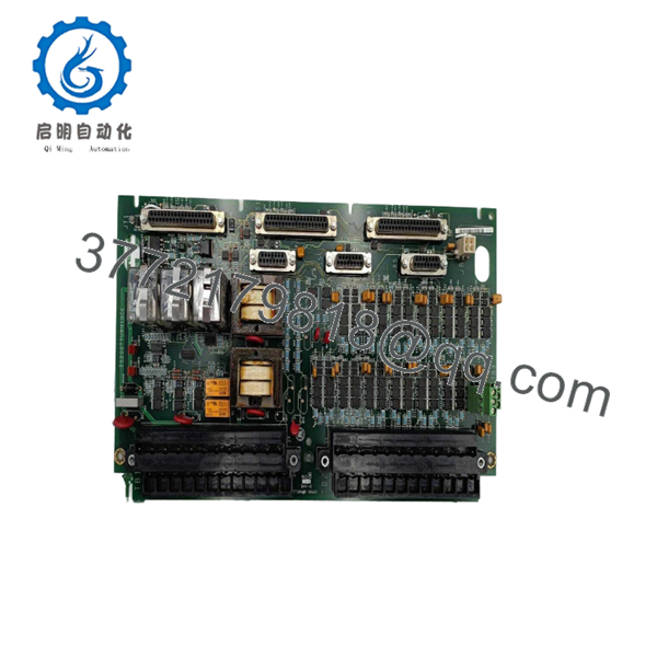
The GE IS200TTURH1BCC is a specialized Turbine Terminal Board designed for the Mark VI Speedtronic control system. It serves as the physical interface for critical speed sensors (magnetic pickups) and provides the necessary hardware for emergency overspeed protection and shaft voltage monitoring. By processing high-speed pulse signals from the turbine shaft, the TTUR ensures the control system can execute emergency shutdowns if speed limits are breached, making it a cornerstone of turbine safety and mechanical integrity.
From a supply chain perspective, the IS200TTURH1BCC represents a high-impact “insurance” component. Because this board handles safety-critical protection loops, utilizing refurbished or used units introduces a risk profile that far exceeds any procurement savings. A failure in the speed sensing circuit can lead to false trips or, worse, a failure to trip during an overspeed event. Acquiring this as New Surplus secures OEM-level reliability and guarantees that the module’s capacitors and pulse-processing circuits have not been subjected to years of thermal stress in a running cabinet.

- IS200TTURH1BCC
- IS200TTURH1BCC
Installation & Configuration Guide
Stage 1: Pre-Installation (Prep & Safety)
- Ensure the turbine is in a safe, de-energized state; this board handles emergency protection and cannot be serviced during operation.
- Verify you have a calibrated digital tachometer/frequency generator for post-installation loop verification.
- Wear a grounded ESD wrist strap throughout the procedure to protect the high-frequency pulse-shaping circuits.
- Record the specific wiring positions on terminal blocks TB1 and TB2, paying close attention to the shield grounding points.
Stage 2: Removal
- Disconnect the 37-pin D-sub cables (JR1, JS1, JT1) from the right side of the board.
- Carefully loosen and remove the field wiring from the terminal barriers.
- Unscrew the mounting fasteners that secure the board to the cabinet’s metal DIN-rail or backplane.
- Remove the board, ensuring the rear of the PCB does not contact any conductive debris.
Stage 3: Installation (Clone & Seat)
- Check the revision code on the new board to ensure it matches the “BCC” suffix of the original unit.
- Mount the IS200TTURH1BCC onto the backplane, tightening all mounting screws to ensure proper frame grounding.
- Re-terminate the field wiring to TB1 and TB2, ensuring high-integrity connections for the magnetic pickup signals to avoid “noise” or dropped pulses.
- Reconnect the D-sub cables, ensuring they are fully seated and the retention screws are tightened.
Stage 4: Power-On & Testing
- Apply logic power to the Mark VI rack and monitor the associated VTUR processor for diagnostic alarms.
- Verify that the shaft speed inputs register “zero” or the expected turning gear speed if applicable.
- Use a frequency generator to simulate a speed signal at the terminal block and verify the reading in the HMI/Toolbox software.
- Confirm the “Healthy” status of the overspeed trip relay circuits before attempting a turbine start.
Firmware/Software Versions & Upgrade Notes
The IS200TTURH1BCC is designed for use within the Mark VI Control ST or Toolbox environment. While terminal boards are primarily passive hardware, they must be compatible with the firmware version resident on the VTUR processor board. The “BCC” version includes specific noise-filtering characteristics optimized for high-sensitivity magnetic pickups. Replacing this with an earlier version (e.g., “AAA”) may lead to signal instability or “ghost” speed readings in high-EMI environments. Ensure that the I/O configuration in your control software matches the hardware revision to prevent configuration mismatch faults during the boot sequence.
Frequently Asked Questions (FAQ)
What does the “BCC” suffix signify on this board?
The suffix indicates the specific revision and build of the board. “BCC” denotes a specific combination of component updates and conformal coating types. In the Mark VI ecosystem, it is vital to match these suffixes during replacement to ensure that the hardware remains transparent to the existing software configuration and physical wiring.
Can I use this board for both MPU and active pulse sensors?
Yes, the IS200TTURH1BCC is designed to handle standard passive Magnetic Pickup Units (MPU) as well as active (powered) pulse sensors. The board conditions these signals into a square wave that the VTUR processor can accurately count.
Why is this board considered a “critical” spare compared to standard I/O?
The TTUR manages the emergency overspeed protection. If this board fails, the turbine’s “last line of defense” against mechanical overspeed is compromised. Maintaining a New Surplus unit on-site allows for immediate restoration of safety-critical protection loops without waiting for OEM lead times.
Are these boards tested for pulse accuracy?
Every New Surplus board we supply undergoes a power-on handshake and signal path verification. We ensure that the frequency processing channels are responsive and that the physical connectors meet OEM tolerances for signal integrity.
Does the board handle shaft voltage monitoring?
Yes, the IS200TTURH1BCC includes dedicated circuitry for monitoring shaft voltage and current. This is essential for detecting grounding issues that can cause catastrophic bearing damage due to electrical discharge machining (EDM).
Is this board “hot-swappable”?
No. Because the TTUR is integral to the emergency trip string, removing it while the system is powered and the turbine is active will immediately initiate an emergency trip (ESTOP) and potentially cause a turbine shutdown. Always perform replacements during a planned outage.


