
 WhatsApp: +86 16626708626
 Email:
  Phone: +86 16626708626
Description
3. Key Technical Specifications
| Parameter | Specification |
| Compatible Probes | Proximitor, Seismic, Accelerometer, Velomitor |
| Number of Channels | 13 to 14 channels (Application dependent) |
| Compatibility | Exclusively interfaces with VVIB VME Board |
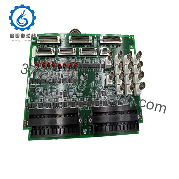
| Connectors | 14 BNC connectors (for portable data gathering) |
| Terminal Blocks | 2 Large pluggable blocks (48 total I/O connections) |
| Voltage Support | -24 VDC output for probe excitation |
| Control Mode | Supports Simplex and TMR (Triple Modular Redundancy) |
| Board Revision | H2B (Revision B Primary) |
| Dimensions | 13.0 in x 7.0 in |
| Temperature Rating | 0 to 60°C (32 to 140°F) |
4. Product Introduction & Supply Chain Strategy
The GE IS200TVIBH2B is the primary termination point for vibration and position sensors within the Speedtronic Mark VI control system. It provides the essential physical connection for Bently Nevada probes used to monitor shaft vibration, thrust wear, and differential expansion. By routing raw analog signals to the VVIB processor board, the TVIB board facilitates real-time diagnostics and enables emergency turbine trips if vibration limits are exceeded.
From a strategic inventory perspective, the TVIB board is an “Insurance Spare.” As Mark VI systems age, these terminal boards are prone to connector oxidation and terminal block fatigue. Because vibration monitoring is a safety-critical function, buying “New Surplus” is a mandatory risk-mitigation strategy. Refurbished terminal boards often have high-impedance joints or micro-corrosion on BNC ports that can trigger “false-trip” alarms or mask real machinery faults. Our New Surplus stock guarantees original signal integrity, protecting your turbine from the six-figure costs of a single unnecessary shutdown.
5. Installation & Configuration Guide
Stage 1: Pre-Installation (Prep & Safety)
Ensure the turbine is in a cold-iron state or that the vibration monitoring core (R, S, or T) is isolated and de-energized. Follow all LOTO procedures for the Mark VI cabinet. Wear a grounded ESD strap. Document the current jumper settings (J1 through J16) on the old board; these define whether the probes are Proximity, Velocity, or Accelerometers.
Stage 2: Removal
Unplug the terminal blocks by loosening the two retaining screws on each. Disconnect the D-shell cables and any BNC diagnostic leads. Carefully unmount the board from its DIN rail or standoff base. Inspect the cabling for any frayed insulation or bent pins in the D-shell connectors.
Stage 3: Installation (Clone & Seat)
Mirror the 16 jumper switches from the old board onto the new IS200TVIBH2B. These jumpers are critical for setting the correct probe bias and sensitivity. Mount the new board and reconnect the terminal blocks. Ensure the pluggable blocks are fully seated before tightening the screws.
Stage 4: Power-On & Testing
Energize the control core. Verify that the VVIB board recognizes the terminal board via the VME bus diagnostics. Perform a “Live Value” check using the Toolbox software to ensure all vibration channels are reporting background noise or static gap voltages consistent with previous readings.
- IS200TVIBH2B
- IS200TVIBH2B
6. Firmware/Software Versions & Upgrade Notes
- VVIB Compatibility: The IS200TVIBH2B is specifically designed to work with the VVIB processor board. It is NOT compatible with the older PVIB modules.
- Hardware Revisions: The H2B revision is a direct replacement for H2A units. It features improved noise suppression and terminal block layout. No software changes are typically required when swapping H2A for H2B.
- Mark VIe Migration: While the IS200TVIBH2B is a Mark VI component, users migrating to Mark VIe often utilize the TVBA board as the modern equivalent. Verify your system architecture if you are planning a control system upgrade.
7. Frequently Asked Questions (FAQ)
Are the BNC connectors used for permanent wiring?
No. The 14 BNC connectors are intended for portable data acquisition equipment. They provide “buffered” signals for maintenance technicians to perform offline vibration analysis without disturbing the permanent control wiring.
Can I use this board for TMR (Triple Modular Redundancy)?
Yes. The TVIB supports TMR configurations where signals are fanned out to three VVIB boards. This is essential for high-availability power generation assets.
What causes a “Probe Fault” alarm on this board?
A fault is typically triggered if the DC voltage from the probe (the “Gap Voltage”) falls outside the predefined limits (usually -2V to -18V for proximity probes). This often indicates a broken wire at the terminal block or a failed probe.
Does this board support 3-wire sensors?
Yes. The terminal blocks are specifically designed to support 3-wire connectivity (Power, Signal, Common) per probe to ensure signal stability over long cable runs.
How is the “H2B” revision different from the base model?
The H2B revision includes updated board artwork and components with higher thermal tolerances. It is fully backward compatible with original Mark VI layouts that utilized the parent IS200TVIBH2 product.


