
 WhatsApp: +86 16626708626
 Email:
  Phone: +86 16626708626
Description
3. Key Technical Specifications
| Parameter | Value |
|---|---|
| Manufacturer | GE General Electric |
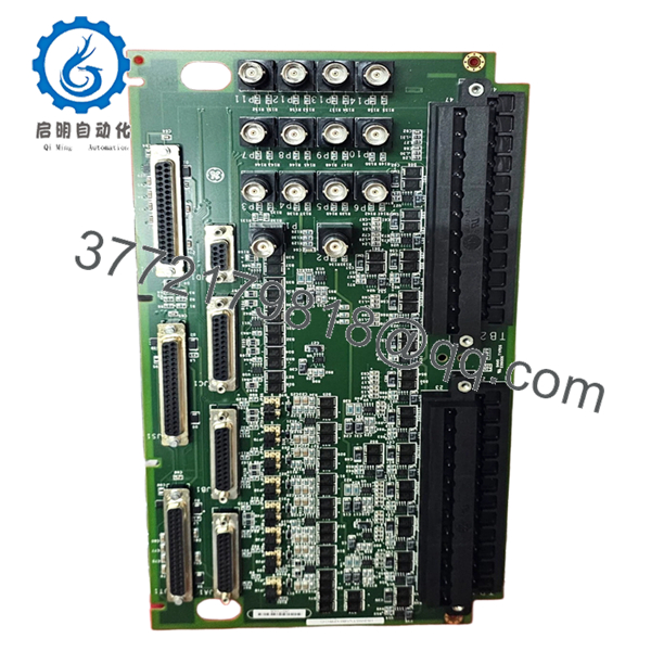
| Model Number | IS200TVIBH2BCC |
| Product Type | Vibration Interface Terminal Board |
| System Platform | GE Mark VI Speedtronic |
| Function | Turbine vibration signal termination |
| Compatible Controllers | Mark VI control racks |
| Input Signal Type | Vibration/transducer interface |
| Mounting Method | Rack/Panel mounted |
| Communication Interface | Backplane interface to Mark VI I/O |
| Operating Temperature | 0 °C to 60 °C typical cabinet environment |
| Storage Temperature | −40 °C to +85 °C |
| PCB Revision | H2BCC revision |
| Condition | New Original / New Surplus |
| Compliance Reference | IEC 61131 industrial control practices |
| Packaging | ESD sealed with reinforced export carton |
4. Product Introduction
The GE IS200TVIBH2BCC is a Mark VI Speedtronic vibration interface terminal board used in turbine control systems for vibration monitoring and signal termination. It interfaces field vibration transducers with the Mark VI control platform in gas and steam turbine applications.
In field deployments, these boards are commonly used during lifecycle extension projects where operators retain existing Mark VI infrastructure instead of migrating immediately to Mark VIe. Engineers typically choose this board to maintain compatibility with installed turbine protection logic and existing cabinet wiring.

- IS200TVIBH2BCC
- IS200TVIBH2BCC
5. Installation & Configuration Guide
Stage 1: Pre-Installation Preparation (Estimated Time: 10 Minutes)
⚠️ Safety First
- Notify operations and obtain maintenance clearance.
- Place the turbine or driven equipment into a safe shutdown state.
- Lock out/tag out all related control cabinet power sources.
- Wait at least 5 minutes for internal capacitors to discharge fully.
Tools Required
- Grounded ESD wrist strap
- PH1 screwdriver
- Fluke 115 multimeter or equivalent
- Wire labels/marker tags
- Smartphone or tablet for wiring photos
- Flashlight for cabinet inspection
Data Backup
- Export existing Mark VI configuration and vibration parameters.
- Record cabinet slot location and associated transducer channels.
- Photograph all terminal wiring and shield grounding points.
- Document jumper positions and hardware revision labels.
❗This is the most common rookie mistake, but it happens constantly. Take photos before touching anything. I’ve seen entire outage windows burned because someone assumed they would “remember the wiring.”
Stage 2: Removing the Old Module (Estimated Time: 5–10 Minutes)
- Remove the front protective cover or cabinet shield if installed.
- Label and disconnect field wiring carefully. Do not yank terminal blocks sideways.
- Release mounting tabs or retaining screws.
- Pull the board straight out to avoid stressing backplane connectors.
- Inspect:
- Backplane pins
- Connector oxidation
- Dust buildup
- Signs of overheating
⚠️ Note
Keep the old module nearby until commissioning is complete. Even failed boards are valuable for confirming jumper layouts and revision matching.
Stage 3: Installing the New Module (Estimated Time: 10 Minutes)
- Wear the ESD strap before opening the anti-static packaging.
- Verify the exact hardware revision: IS200TVIBH2BCC.
- Inspect the PCB for:
- Bent connector pins
- Shipping damage
- Loose terminal blocks
Configuration Clone (Crucial)
- Replicate every jumper and switch position exactly.
- Verify shield grounding points match the original installation.
- Confirm vibration channel assignments against the OEM drawings.
❗I’ve seen projects where a technician swapped in a newer revision board and spent two days chasing intermittent alarms. The root cause was one factory-default jumper setting that changed the signal reference configuration.
Physical Installation
- Insert the board evenly into the rack guides.
- Push firmly until fully seated.
- Tighten retaining hardware evenly.
- Reconnect field wiring using proper terminal torque.
Self-Checklist
- Hardware revision verified
- Jumpers match original
- Wiring secured
- Shield grounds restored
- Mounting tabs locked
Stage 4: Power-On & Testing (Estimated Time: 15–20 Minutes)
Pre-Power Check
- Use a multimeter to verify no short exists on the 24 V rail.
- Check continuity of grounding points.
- Confirm shield drain wiring is not accidentally grounded at multiple points.
Power-On Steps
- Power the Mark VI rack first without enabling field devices.
- Observe diagnostic LEDs.
- Green RUN: Normal initialization
- Red ERR: Hardware or communication issue
- Connect the engineering workstation.
- Verify:
- Board recognition
- Channel status
- Hardware diagnostics
- Firmware compatibility
- Restore application configuration if required.
- Perform dry-run signal simulation before returning equipment to service.
⚠️ Troubleshooting Notes
- Solid ERR LED: Suspect firmware or hardware revision mismatch.
- Intermittent vibration alarms: Check shield grounding and transducer polarity.
- No communication: Verify rack slot assignment and backplane seating.
Even within GE Mark VI systems, terminal assignments and grounding schemes changed between some hardware revisions. Never wire from memory.
Technical Pitfalls & Survival Guide
❗ Firmware Revision Mismatch
A newer replacement board may not behave identically with older Mark VI firmware baselines.
Before removing the old board:
- Record firmware revisions
- Document rack configuration
- Verify compatibility range with the turbine control engineer
I once saw a plant lose 18 hours during startup because the replacement board revision expected a different diagnostic handshake timing from the existing controller.
❗ DIP Switch / Jumper Errors
Factory defaults rarely match plant settings.
Before removal:
- Take high-resolution photos
- Zoom in on every jumper
- Label anything ambiguous
One missed termination jumper can create unstable vibration readings that look like a failing bearing.
❗ Terminal Block Differences
Some H-series revisions use different terminal labeling conventions.
Always:
- Verify pinouts against the OEM drawing
- Confirm shield grounding method
- Check transducer excitation wiring carefully
Do not assume similar GE boards share identical terminal layouts.
❗ Power Budget Problems
Replacement boards can alter cabinet loading slightly.
Verify:
- Rack power supply headroom
- Total backplane current
- Cabinet thermal conditions
Leave at least a 20% power margin on the control supply.
❗ Electrostatic Discharge (ESD)
These boards are extremely vulnerable during dry winter conditions.
Use:
- Grounded wrist strap
- ESD mat
- Anti-static storage bags
I watched a contractor unpack a Mark VI board without grounding himself. Installed it, powered it up, and the diagnostics failed immediately. That mistake cost the outage schedule an extra day.
Keep these checks in mind and you’ll save yourself 90% of typical rework time.
6. Frequently Asked Questions (FAQ)
Q1: Can I hot-swap the GE IS200TVIBH2BCC under power?
No. Mark VI terminal and interface boards are not designed for hot swapping during normal plant operation. Pulling the board live can damage the backplane or trigger false turbine protection trips. Shut down cabinet power first.
Q2: Is the IS200TVIBH2BCC obsolete?
Yes. The Mark VI platform is considered a legacy GE control family. Many utilities and industrial plants still operate it, but OEM production is limited. Availability depends heavily on surplus inventory and lifecycle recovery stock.
Q3: Is this unit genuinely new or refurbished?
This inventory is classified as New Original / New Surplus. That generally means unused OEM-manufactured stock stored in controlled inventory, not repaired field returns.
We still perform:
- Visual inspection
- Communication verification
- Electrical testing
- ESD-controlled packaging
Test reports, serial photos, and inspection records are available upon request.
Q4: Will I lose my turbine logic if I remove this board?
Normally, no. The IS200TVIBH2BCC itself does not store primary turbine application logic like the controller CPU does. However, always back up the Mark VI configuration before maintenance work. I’ve seen engineers assume “it’s only an I/O board” and still end up rebuilding channel mappings after a rushed swap.
Q5: What should I verify before ordering a replacement?
At minimum:
- Exact part number
- Hardware revision
- Terminal configuration
- Existing firmware baseline
- Cabinet slot location
GE revisions matter. One missing suffix can create wiring or compatibility problems.
Q6: Why is your pricing lower than current OEM support channels?
Most available Mark VI inventory now comes from surplus channels, plant decommissioning projects, or long-term distributor stock rather than fresh OEM production runs. Pricing varies based on stock age, traceability, and test coverage.
Lower price does not automatically mean counterfeit. What matters is:
- Traceability
- Inspection records
- Functional testing
- Proper ESD handling
Q7: Do you provide functional testing documentation?
Yes. Boards are typically tested on a compatible Mark VI rack or simulation setup before shipment.
Standard verification includes:
- Power-on diagnostics
- Communication checks
- Connector inspection
- Basic I/O verification
- 24-hour observation run where applicable
Photos and test videos are available upon request.


