
 WhatsApp: +86 16626708626
 Email:
  Phone: +86 16626708626
Description
3. Key Technical Specifications
| Parameter | Value |
|---|---|
| Manufacturer | General Electric (GE) |
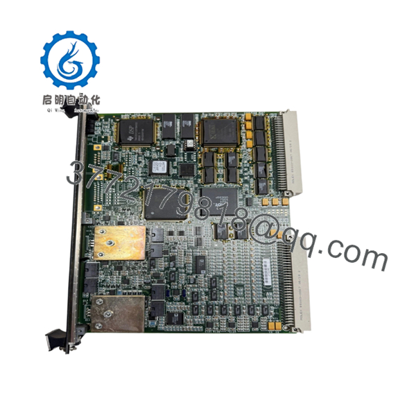
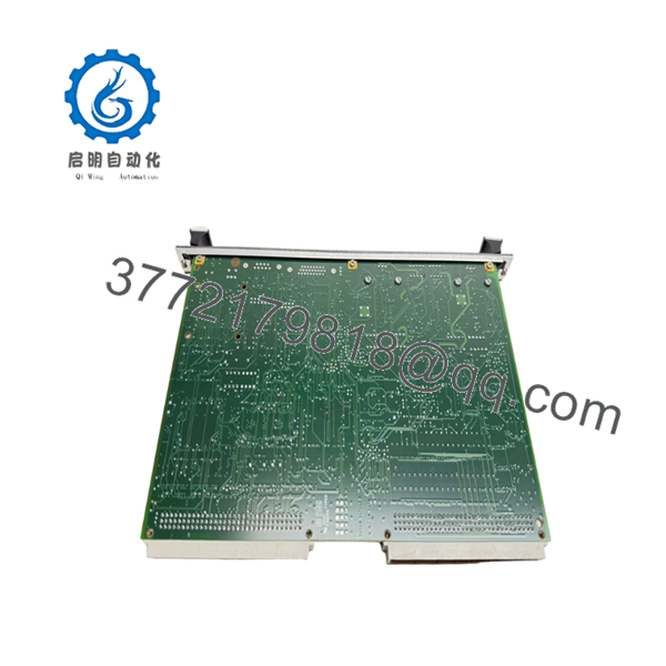
| Model | IS200VAICH1DAB |
| Functional Abbreviation | VAIC |
| Product Series | Mark V Speedtronic |
| Product Type | Analog Input/Output Board |
| Mounting Platform | VME Rack |
| Analog Inputs | Up to 20 channels |
| Input Signals | ±10 V DC, ±5 V DC, 4–20 mA, ±1 mA (configuration dependent) |
| Analog Outputs | 4 channels |
| Output Signals | 4–20 mA; selected outputs configurable for higher current ranges |
| Converter Type | A/D converter and D/A converter |
| Scan Time | 10 ms normal scan (100 Hz) |
| Manual Reference | GEH-6421 |
| Typical Application | Turbine control, process monitoring, industrial automation |
| Configuration Type | Simplex or TMR architecture |
Technical specifications are based on available GE Mark V documentation references and industrial inventory records. Verify exact revision compatibility against the OEM documentation before installation.
4. Product Introduction
The GE IS200VAICH1DAB is a Mark V Speedtronic Analog Input/Output Board designed for GE turbine control applications. The VAIC board processes field analog signals, performs signal conditioning, and provides analog outputs for turbine control loops. It is installed in GE VME control racks used in gas turbine and steam turbine systems.
The module supports simplex and TMR configurations, including applications where multiple VAIC boards participate in redundant control architectures. Its analog input density and configurable output channels make it a common replacement part for legacy GE Mark V installations.
5. Installation & Configuration Guide
Stage 1: Pre-Installation Preparation (Approx. 10 minutes)
⚠️ Safety First
- Notify operations before removing the existing GE module.
- Place the turbine/control system into an approved maintenance state.
- Apply lockout/tagout procedures.
- Verify power isolation and wait at least 5 minutes for capacitor discharge.
Tools Required
- ESD wrist strap
- PH1 screwdriver
- Digital multimeter
- Wire labels
- Smartphone/camera for configuration records
Data Backup
- Export existing Mark V configuration data if available.
- Record rack position and board location.
- Photograph:
- Terminal wiring
- Jumpers
- Board identification labels
- Existing module position
Stage 2: Removing the Old Module (Approx. 10 minutes)
- Remove the front cover or protective bezel.
- Label all connected wiring before removal.
- Disconnect terminals carefully. Do not pull wires by force.
- Release rack retention hardware.
- Pull the board straight out to avoid damaging VME backplane contacts.
⚠️ Important: Keep the removed IS200VAICH1DAB until the replacement unit has passed testing.
Inspect:
- VME connector pins
- Rack contacts
- Dust contamination
- Signs of overheating
Stage 3: Installing the New Module (Approx. 10 minutes)
- Wear an ESD wrist strap before handling the board.
- Confirm the replacement part number:
Old: IS200VAICH1DAB
New: IS200VAICH1DAB
- Compare:
- Revision label
- Jumpers
- Terminal configuration
- Insert the board into the correct VME rack slot.
- Confirm the board is fully seated.
- Reconnect field wiring using the original labels.
Self-Checklist
- Correct model number verified
- Board seated correctly
- Wiring restored
- Rack hardware locked
Stage 4: Power-On & Testing (Approx. 15–30 minutes)
Pre-Power Check
- Measure supply voltage.
- Check for unexpected shorts.
- Verify wiring polarity.
Power-On Sequence
- Power the control rack first.
- Observe board status indicators.
- Confirm the Mark V controller recognizes the VAIC board.
- Verify configuration parameters.
- Perform analog input simulation testing.
- Verify output loop operation.
⚠️ Troubleshooting Note
If the system reports a board fault:
- Check firmware/revision compatibility.
- Verify rack slot assignment.
- Confirm terminal board compatibility.
- Compare old and replacement jumper settings.

- IS200VAICH1DAB
- IS200VAICH1DAB
6. Frequently Asked Questions (FAQ)
Q1: Can the GE IS200VAICH1DAB be hot-swapped under power?
Generally, do not assume hot-swap capability. The IS200VAICH1DAB is a VME-based Mark V control board, and removing boards under power can damage backplane connections or create control faults. Follow the GE maintenance procedure for your specific cabinet configuration.
Q2: Is the IS200VAICH1DAB obsolete?
Yes. The Mark V platform is a legacy GE turbine control system. Availability depends on surplus inventory, refurbished stock, and exchange programs. Always verify revision and physical condition before purchase.
Q3: Will I lose the turbine control logic when replacing this board?
No, the control logic is normally stored in the Mark V control system configuration, not inside the analog I/O board itself. However, channel calibration and jumper settings must match the original installation.
Q4: What is the direct replacement for IS200VAICH1DAB?
There is no universal drop-in replacement across all applications. The correct replacement depends on:
- Mark V cabinet type
- Simplex/TMR architecture
- Terminal board type
- Existing firmware and configuration
Verify with the OEM manual before substitution.
Q5: Why is surplus IS200VAICH1DAB pricing lower than OEM pricing?
Legacy GE turbine control parts are often sourced from surplus inventories or tested exchange stock. Lower pricing does not automatically indicate lower quality, but buyers should confirm inspection records, test reports, and warranty terms.
Q6: What inspection should be completed before installation?
A proper inspection should include:
- Serial number verification
- PCB visual inspection
- Connector condition check
- Power-up test
- Communication verification
- Analog channel simulation test
Q7: What condition should I request when buying this module?
For critical turbine applications, request clear condition wording:
- New Original / New Surplus
- Factory Sealed (if applicable)
- Refurbished (tested)
Avoid unclear descriptions such as “used good” without test documentation.


