
 WhatsApp: +86 16626708626
 Email:
  Phone: +86 16626708626
Description
Key Technical Specifications
| Parameter | Specification Value |
| Manufacturer | GE (General Electric) |
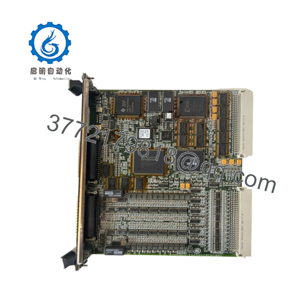
| Part Number | IS200VCRCH1B / IS200VCRCH1BBC |
| System Architecture | Speedtronic Mark VI Turbine Control |
| Board Type | VME Compact Rear Cabling (VCRC) |
| Form Factor | 3U single-slot VME width |
| Cabling Support | High-density ribbon and multi-conductor cables |
| Connector Type | DIN 41612 standard backplane connectors |
| Operating Temperature | 0 to +60 °C (32 to 140 °F) |
| Storage Temperature | −40 to +85 °C (−40 to 185 °F) |
| Relative Humidity | 5% to 95% non-condensing |
Product Introduction & Supply Chain Strategy
The GE IS200VCRCH1B functions as a VME Compact Rear Cabling (VCRC) board within the Mark VI Speedtronic turbine control system. It acts as the physical and electrical interface that handles signal distribution between the active VME processing cards and the external terminal blocks. By providing clean, dedicated connection paths at the rear of the rack, this board ensures reliable signal transfer for mission-critical steam or gas turbine applications.
Securing this hardware as New Surplus is a necessary action for plant managers aiming to control Total Cost of Ownership (TCO). Because the Mark VI system faces diminished factory support, relying on refurbished components introduces significant failure points via degraded connectors and micro-fractures. Maintaining 1–2 units of this genuine item on-site serves as an essential insurance policy, shielding your operation from stock-out incidents and avoiding the massive financial loss of unplanned generation downtime.

- IS200VCRCH1B
- IS200VCRCH1B
Installation & Configuration Guide
Stage 1: Pre-Installation (Prep & Safety)
- Isolate the target VME rack and execute standard lock-out/tag-out procedures on the power feeds.
- Put on a grounded, static-dissipative wrist strap connected to the enclosure frame to prevent ESD damage.
- Label all connected rear ribbon cables clearly, and photograph the exact cable routing and orientation.
Stage 2: Removal
- Loosen the upper and lower retaining screws on the existing rear cabling board using a standard screwdriver.
- Disconnect all interface cables gently, pulling straight out on the connector bodies to prevent strain on the pins.
- Grip the edges of the card and pull straight outward along the rack guides to ensure backplane pins do not bend.
Stage 3: Installation (Clone & Seat)
- Inspect the new surplus board for any dust or pin alignment issues before installation.
- Check any hardware jumper blocks on the new board and position them to match the exact configuration of the pulled unit.
- Slide the board into the designated rear chassis track, pushing firmly until the DIN connectors seat fully into the backplane.
- Tighten the retaining screws to secure the card mechanically. Reconnect all signal cables per your labels and pre-removal photographs.
Stage 4: Power-On & Testing
- Use a digital multimeter to confirm that the 24 V DC supply rails are stable and free of short circuits before energizing the rack.
- Restore power to the VME chassis and verify that neighboring processor cards complete their power-on self-test without communication errors.
- Check the HMI diagnostics to confirm that the physical I/O channels routed through this board match real-world field values.
Firmware/Software Versions & Upgrade Notes
As a passive signal routing board, the IS200VCRCH1B does not host active onboard flash firmware. However, its hardware revision level—denoted by the “H1B” or “H1BBC” suffix—must match the physical spacing and trace requirements of your existing active processor cards.
When replacing an older revision, confirm that the physical pin layouts match the existing cable harnesses. Attempting to mix incompatible board revisions can alter the signal paths, leading to protocol timeouts or false diagnostics within the control system logic. Always back up the active controller configuration using your Toolbox software before replacing any connected backplane or routing components.
Frequently Asked Questions (FAQ)
Q: Why is this unit priced higher than a refurbished board, but lower than OEM list? A: This unit is verified New Surplus inventory sourced from secure global channels. Refurbished boards are typically cleaned up cosmetically, but they carry hidden component fatigue and micro-cracks that compromise plant reliability. Our pricing reflects the market cost of delivering genuine, unused OEM hardware that guarantees a 10–15 year operational lifespan, providing total peace of mind at a cost well below original factory pricing.
Q: Are these boards actual genuine new items, and how is that verified? A: Yes, these are completely original, unused items. They are received in original anti-static packaging, which is only opened under strict ESD-safe laboratory conditions for quality control testing and inspection. We confirm authenticity via physical serial number matching, OEM packing list tracking, and thorough backplane pin wear checks.
Q: What is the obsolescence and EOL status of the IS200VCRCH1B? A: The GE Mark VI series is classified as a legacy control platform, meaning new production has ceased. Because of this lifecycle status, getting items directly from the OEM involves long lead times and high costs. We maintain these specific boards in our stock to support strategic buffer stock programs for active plants.
Q: Can this cabling board be hot-swapped while the turbine control system is running? A: No. You must never hot-swap the rear cabling board while the VME rack is energized. Removing or inserting this board while power is applied can cause voltage arcs across the backplane pins, which can ruin the routing board and permanently damage adjacent processing cards.
Q: Does this board require separate software programming or memory configuration? A: No software programming is stored directly on this board. It serves as a physical bridge for signals. However, you must verify that any hardware jumpers or DIP switches match your original board configuration so that signals map correctly to the system logic.
Q: What warranty is provided with this New Surplus board? A: We back this product with a comprehensive 1-year commercial replacement warranty. This covers all internal circuitry and connector performance, providing identical protection to original factory components without the extended lead times.


