
 WhatsApp: +86 16626708626
 Email:
  Phone: +86 16626708626
Description
3. Key Technical Specifications
| Parameter | Value |
|---|---|
| Manufacturer | General Electric (GE) |
| Model Number | IS200VCRCH1BBA |
| Functional Acronym | VCRC |
| Product Type | Discrete Input/Output Processor Board |
| Series | Mark VI Speedtronic Turbine Control System |
| Rack Type | VME I/O Rack |
| Discrete Inputs | 48 Contact Inputs |
| Relay Outputs | 24 Relay/Solenoid Outputs |
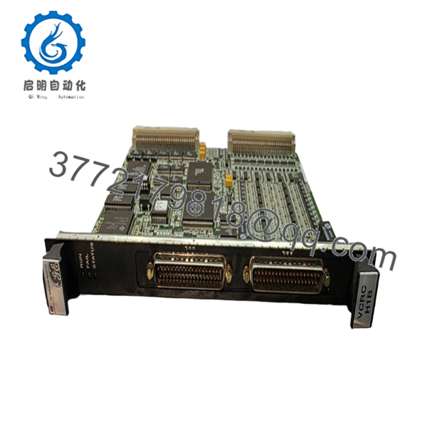
| Front Connectors | J33, J44 |
| Status LEDs | RUN (Green), FAIL (Red), STATUS (Orange) |
| Revision Level | BBA |
| Backward Compatibility | First two revisions compatible |
| Application Type | Simplex and TMR Systems |
| Operating Temperature | 0 °C to 60 °C |
| Isolation Method | Optical Isolation |
| SOE Resolution | 1 ms Event Recording |
| Pulse Detection | Down to 6 ms |
| Mounting | Single-Slot VME Rack Module |
| Country of Manufacture | USA |
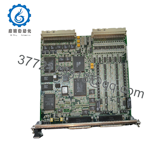
The IS200VCRCH1BBA is a single-slot VCRC board used in GE Mark VI turbine control systems. It provides the same functional capability as the larger VCCC board while reducing rack space requirements. The module processes 48 discrete inputs and controls 24 relay outputs through associated TBCI and TRLY terminal boards.
4. Product Introduction
The GE IS200VCRCH1BBA is a Mark VI VCRC discrete input/output processor board designed for Speedtronic gas and steam turbine control systems. It mounts in a VME I/O rack and manages field contact inputs, relay outputs, event monitoring, and protection logic.
Engineers typically select the VCRC when rack space is limited. Unlike the dual-slot VCCC design, the IS200VCRCH1BBA occupies a single slot while maintaining equivalent I/O functionality. It supports simplex and TMR architectures and provides 1 ms sequence-of-events recording for critical turbine applications.

- IS200VCRCH1BBA
- IS200VCRCH1BBA
5. Installation & Configuration Guide
Stage 1: Pre-Installation Preparation (10 Minutes)
⚠️ Safety First
- Notify operations and obtain maintenance clearance.
- Place the turbine or controlled process in a verified safe state.
- Apply lockout/tagout procedures to all control cabinet power sources.
- Wait at least 5 minutes for power supply capacitors to discharge.
- Verify zero voltage using a calibrated multimeter.
Tools Required
- Grounded ESD wrist strap
- PH1 screwdriver
- Fluke 115 or equivalent multimeter
- Wire labels
- Smartphone or digital camera
- Flashlight
- Anti-static work surface
Data Backup
- Export current controller logic and configuration.
- Document all IP addresses and controller node assignments.
- Photograph:
- VCRC front panel
- J33/J44 cable connections
- Terminal board wiring
- Any jumper or switch settings
- Record firmware revisions from the existing controller.
❗ Firmware revision documentation matters. I’ve seen Mark VI replacements fail commissioning because the replacement board carried a later revision than the original system architecture expected.
Stage 2: Removing the Old Module (5 Minutes)
- Remove cabinet covers as required.
- Label all field cables before disconnecting.
- Disconnect J33 and J44 connectors carefully.
- Release rack retaining clips.
- Pull the board straight out.
⚠️ Do not rock the board side-to-side excessively. VME backplane connectors can be damaged by uneven removal force.
- Inspect:
- Backplane pins
- Connector alignment
- Dust accumulation
- Corrosion or moisture damage
⚠️ Keep the original board on-site until commissioning is complete. It remains your quickest troubleshooting reference.
Stage 3: Installing the New Module (10 Minutes)
1. ESD Preparation
- Wear grounded wrist strap.
- Place board on ESD mat.
- Verify model number reads exactly:
- IS200VCRCH1BBA
2. Configuration Clone (Critical)
Compare all settings against photographs taken before removal.
Verify:
- Node addressing
- Rack position
- Associated terminal board configuration
- TMR architecture assignment if applicable
❗ This is the most common rookie mistake, but it happens constantly. Take a picture before you pull it. I can’t stress this enough.
3. Install Module
- Align board with card guides.
- Insert evenly into rack.
- Push until fully seated.
- Engage locking tabs.
You should feel a positive connector engagement.
4. Reconnect Cabling
- Reconnect J33.
- Reconnect J44.
- Verify connector latching.
- Inspect cable routing.
Self-Checklist
- Model number verified
- DIPs/jumpers matched
- J33 connected
- J44 connected
- Board fully seated
- Locking tabs engaged
Stage 4: Power-On & Testing (10-15 Minutes)
Pre-Power Check
- Measure resistance across the 24 V rail.
- Verify no direct shorts exist.
- Inspect cabinet grounding.
Power-Up Sequence
- Energize control rack power only.
- Observe startup LEDs.
Expected indications:
- RUN LED = Green
- FAIL LED = Off
- STATUS LED = Off or diagnostic dependent
- Connect ToolboxST or applicable GE engineering software.
- Verify:
- Board detection
- Rack location
- Firmware revision
- I/O communication status
- Restore configuration if required.
- Execute dry-run I/O verification.
Test:
- Contact inputs
- Relay outputs
- Alarm generation
- Event logging
⚠️ Troubleshooting Note
- Solid Red FAIL LED: Suspect firmware mismatch or hardware fault.
- No Communications: Verify VME rack addressing, controller communication path, and connector seating.
- Intermittent Inputs: Check TBCI terminal board wiring and grounding.
Common Field Pitfalls Engineers Encounter
❗ Firmware Revision Mismatch
A newer replacement board may carry firmware that behaves differently than the existing controller environment.
I’ve seen a turbine trip investigation consume two days because a replacement module jumped from an earlier revision to a later build. Communications initialized but diagnostic polling repeatedly timed out.
Avoidance: Record firmware before removal and request matching revision ranges when ordering.
❗ DIP Switch and Jumper Errors
Many outages start here.
Factory settings rarely match site settings.
Avoidance: Photograph everything before removal and duplicate settings exactly.
❗ Terminal Board Compatibility
Even within Mark VI hardware families, associated terminal board revisions can differ.
Avoidance: Verify TBCI and TRLY documentation before energizing.
Never wire from memory.
❗ Power Supply Capacity
Replacement projects often ignore rack loading.
For example, adding multiple I/O cards can push a marginal 24 V supply beyond acceptable limits.
Avoidance: Calculate total cabinet consumption and maintain at least 20% capacity margin.
❗ Electrostatic Discharge (ESD)
I once watched a contractor unpack a turbine board during winter without a wrist strap. The board powered up once, emitted smoke, and never booted again.
Avoidance: Wrist strap, grounded mat, anti-static packaging. Every time.
Keep these checks in mind and you’ll save yourself 90% of typical rework time.
6. Frequently Asked Questions (FAQ)
Q1. Can I hot-swap the IS200VCRCH1BBA?
No.
The IS200VCRCH1BBA is installed on a VME rack backplane. Removing or inserting it under power risks connector arcing, backplane damage, and controller communication faults.
Shut down rack power before replacement.
Q2. Is the IS200VCRCH1BBA obsolete?
Yes.
Mark VI systems remain active worldwide, but the IS200VCRCH1BBA is no longer a current-production GE control platform component.
Most available inventory today consists of:
- New Surplus
- Factory Spare Stock
- Professionally Refurbished Units
Availability can change quickly due to turbine outage demand.
Q3. What is the direct replacement for the IS200VCRCH1BBA?
The closest functional equivalent is the VCCC family used in the same Mark VI architecture.
However, VCCC is a dual-slot design while VCRC is single-slot. Physical installation requirements differ.
Verify rack layout and terminal board compatibility before substitution.
Q4. Will I lose my application logic when I remove this board?
Normally no.
Control logic resides within the controller system, not inside the VCRC I/O processor board itself.
Still, always perform a complete backup before maintenance. Never assume documentation is current.
Q5. Why are New Surplus units often cheaper than OEM channels?
Most New Surplus inventory originates from:
- Cancelled projects
- Strategic spare-part programs
- Plant decommissioning stock
- Distributor excess inventory
The hardware is unused but may have been stored for years. That is why incoming inspection and electrical testing matter.
Q6. What testing should be performed before shipment?
A proper inspection process should include:
- Serial number verification
- Visual inspection for corrosion and rework marks
- Power-on testing on a genuine Mark VI rack
- Communication handshake verification
- I/O simulation testing
- 24-hour load testing
- 500 V insulation resistance testing (>10 MΩ)
- Firmware version documentation
- Final QC sign-off
Test reports, photos, and videos should be available upon request.
Q7. What condition should I choose: New Surplus or Refurbished?
For critical turbine outage spares, New Surplus is generally preferred when available.
A properly tested refurbished unit can still be a practical option, especially for emergency shutdown inventory or budget-constrained facilities.
The important question is not “new or refurbished.”
The important question is whether the supplier can provide documented testing results, firmware verification, and traceability records. That’s what determines whether the board is likely to run reliably after installation.


