

 WhatsApp: +86 16626708626
 Email:
  Phone: +86 16626708626
Description
3. Key Technical Specifications
| Parameter | Value |
|---|---|
| Model | IS200VTCCH1CBB |
| Brand | GE (General Electric) |
| Series | Mark VI Speedtronic |
| Board Type | Thermocouple Input Terminal Board / VTCC (VME Thermocouple Conditioner) |
| Input Channels | 24 thermocouple inputs |
| Thermocouple Types | E, J, K, S, T (and mV input) |
| mV Input Range | -8 mV to +45 mV |
| Input Configuration | Grounded or ungrounded thermocouples |
| Maximum Cable Distance | 300 meters (984 feet) |
| Loop Resistance Max | 450 Ω (bidirectional) |
| Cold Junction Compensation | 2 onboard CJC sensors |
| Terminal Board Compatibility | DTTC (DIN rail) or TBTC (TMR capable) |
| Redundancy Support | Simplex (TBTCH1C) or TMR (TBTCH1B) |
| Backplane Connectors | P1 and P2 (VME bus) |
| Key Components | Xilinx XCS30 FPGA, TMS320C32PCMA50 DSP, IDT SRAM |
| Status LEDs | 3 LEDs (stacked near top edge) |
| Operating Temp | -20°C to +60°C (-4°F to 140°F) |
| Storage Temp | -40°C to +85°C (-40°F to 185°F) |
| Humidity | 5% to 95% non-condensing |
| Coating | Conformal coated (for harsh environments) |
| Dimensions (approx) | 6.6 x 5.9 x 2.2 inches (167 x 150 x 56 mm) |
| GE Part Family | IS200 (Mark VI) |
| Reference Manual | GEH-6421 |
4. Product Introduction
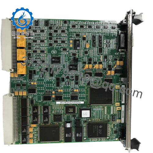
The GE IS200VTCCH1CBB is the VTCC thermocouple input board for the Mark VI Speedtronic turbine control system. This board acquires up to 24 thermocouple signals from gas and steam turbine hot gas path components — exhaust thermocouples, bearing temperature sensors, inlet air temperature, and metal temperature detectors.
The VTCC board conditions E, J, K, S, and T type thermocouples as well as direct mV inputs (-8mV to +45mV range). It includes onboard cold junction compensation (two CJC sensors) and feeds processed data to the Mark VI controller over the VME backplane. The board supports both simplex and TMR (triple modular redundant) configurations depending on the connected termination board (TBTC or DTTC series). If your Mark VI system is reporting erratic temperature readings or open thermocouple faults, this board is the primary suspect.
5. Installation & Configuration Guide
Estimated time for replacement by a qualified technician: 35 minutes
Stage 1: Pre-Installation Preparation (10 minutes)
⚠️ Safety First: Notify operations of turbine shutdown. Verify the turbine is offline and control power is locked out. Wait 5 minutes for capacitors to discharge.
Tools Required:
- ESD wrist strap (grounded to earth)
- Small flathead screwdriver (for terminal block connections)
- Multimeter with thermocouple mV capability (optional, for signal injection)
- Smartphone for photos
- Needle-nose pliers (for jumper adjustments)
Data Backup:
- Document which thermocouple type is configured for each channel (E, J, K, S, T, or mV). This is typically in the Mark VI configuration file.
- Take a high-resolution photo of the board showing:
- All jumper positions (J3, J4 for CJC reference selection)
- Any DIP switches (if present on your specific revision)
- Note the associated termination board type (DTTC or TBTC) and its configuration.
Stage 2: Removing the Old Module (10 minutes)
Step 1: Locate the VTCC board in the Mark VI rack. It connects to a DTTC or TBTC termination board via a ribbon cable.
Step 2: Remove the front panel cover (if equipped).
Step 3: Disconnect the ribbon cable from the VTCC board. Squeeze the locking tabs gently — do not pull on the wires.
Step 4: Release the board ejectors (top and bottom). Pull the board straight out of the VME backplane. No rocking — this bends backplane pins.
Step 5: Inspect the backplane connector. Look for bent pins, corrosion, or debris.
Step 6: Keep the old board on an ESD mat as a reference.
Stage 3: Installing the New Module (10 minutes)
Step 1 (ESD): Ground your wrist strap. Unpack the new IS200VTCCH1CBB on an ESD mat.
Step 2 (Verify Model): Confirm the new board label reads IS200VTCCH1CBB exactly. The “CBB” suffix is critical — earlier revisions (e.g., CBA) may have different CJC characteristics.
Step 3 (Clone Configuration — Critical):
- Set all jumpers (J3, J4) to match the old board. These select local vs. remote cold junction reference.
- If your board has DIP switches, set them to match the photo.
Step 4: Insert the board into the original VME slot. Push evenly until both ejectors latch. Listen for the click.
Step 5: Reconnect the ribbon cable to the termination board. Ensure the locking tabs engage.
Step 6: Reinstall the front panel cover.
Self-Checklist:
- Board fully seated (ejectors locked)
- J3 and J4 jumper positions verified
- Ribbon cable secured
- Termination board connections tight (field wiring side)
Stage 4: Power-On & Testing (5 minutes)
Pre-Power Check:
Verify no tools or debris remain inside the rack. Check that all termination board screws are tight — loose connections cause open thermocouple faults.
Power-On Steps:
- Apply control power to the Mark VI rack.
- Observe the three status LEDs on the VTCC board (stacked near the top edge):
- LED 1 (Power/Ready): Should be steady on.
- LED 2 (Run/Active): Should blink or remain steady depending on configuration.
- LED 3 (Fault): Should be off.
- Access the Mark VI operator interface (ToolboxST or CIMPLICITY). Navigate to the temperature monitoring screen.
- Verify all 24 thermocouple channels report expected values (ambient temperature for uninstalled channels, or actual turbine temperatures).
- For any channel reading “OPEN” or “FAIL”:
- Check field wiring at the termination board.
- Inject a known mV signal (e.g., 0 mV = 0°C for type K) to verify the channel.
⚠️ Troubleshooting:
| Symptom | Likely Cause | Action |
|---|---|---|
| All LEDs off, no communication | Backplane power missing or board not seated | Reseat board. Check rack power supply. |
| Fault LED on steady | CJC failure or configuration mismatch | Verify J3/J4 jumpers match old board. Replace if fault persists. |
| One channel reads “OPEN” | Thermocouple wire broken or termination loose | Check field wiring. Tighten terminal screws. |
| Multiple channels read erratic | Ground loop or CJC reference wrong | Verify thermocouples are grounded at one point only. Check J3/J4 setting. |
| All channels read 20-30°C offset | CJC sensor failure | Replace board. CJC is not field-replaceable. |
| Temperature readings noisy | Shield not grounded or cable too long | Ground shield at termination board only. Keep cables under 300m. |

- IS200VTCCH1CBB
6. Frequently Asked Questions (FAQ)
Q: Is the IS200VTCCH1CBB a direct replacement for older VTCC boards like IS200VTCCH1CBA?
A: Yes, with verification of configuration. The “CBB” suffix indicates a specific hardware revision and conformal coating variant. It is backward compatible with earlier revisions (CBA). However, the CJC calibration may differ slightly. After replacement, verify a known-good thermocouple channel against a calibrated reference. Adjust the configuration offset in ToolboxST if needed. We can provide calibration data for the specific board we ship.
Q: Can I use this board in a TMR (triple modular redundant) system?
A: Yes, but you need the correct termination board. For TMR operation (three VTCC boards voting on the same thermocouple inputs), you must use the TBTCH1B termination board. For simplex operation (single VTCC board), use TBTCH1C or DTTC. The IS200VTCCH1CBB itself is identical for both applications — the redundancy is handled by the termination board and the Mark VI controller’s voting logic.
Q: What happens if a thermocouple exceeds the hardware limits?
A: The VTCC board will automatically remove that channel from the scan. This prevents a failed thermocouple (shorted or open) from corrupting other inputs through ground loops or excessive common-mode voltage. The Mark VI controller will report a “Thermocouple Out of Range” fault. Check your field wiring and thermocouple integrity before condemning the board.
Q: Can I hot-swap the VTCC board while the turbine is running?
A: No. The Mark VI backplane has live power and communication signals. Hot-swapping can cause voltage spikes on the VME bus, potentially damaging the board or the backplane. Procedure: Shut down the turbine, lock out control power, wait 30 seconds, then swap. After replacement, reload the configuration from backup and verify all channels before restarting.
Q: How do I bench test the VTCC board without a Mark VI rack?
A: You need a +5V power supply, a VME backplane (or test fixture), and a thermocouple simulator. This is complex for field use. The simpler approach: Install the board in a known-good Mark VI rack and inject mV signals at the termination board. For a 0 mV input (0°C for type K), the controller should read 0°C ±2°C. We can provide a test report from our Mark VI test stand instead.
Q: Why does my Mark VI show “CJC Fail” after replacement?
A: The cold junction compensation sensor is calibrated at the factory. The error indicates either:
- Jumper mismatch — J3/J4 select local vs. remote CJC reference. Verify they match the old board.
- Faulty CJC sensor — The onboard sensor has drifted or failed. This requires board replacement. The CJC is not field-repairable.
Q: What’s the difference between VTCC and other Mark VI temperature boards?
A: Quick reference:
- VTCC (IS200VTCCH1CBB): Thermocouple input (E,J,K,S,T) and mV. 24 channels. Most common for gas turbine exhaust and bearing temps.
- RTCC (IS200RTCC): RTD input (Pt100, Ni120) for bearing and winding temperatures.
- TCI (IS200TCI): Thermocouple input with isolated channels for high-noise environments.
- TCCA (IS200TCCA): Thermocouple conditioner with cold junction on the termination board (remote CJC).
The VTCC is the standard thermocouple board for most Mark VI installations. If you have RTDs, use RTCC.
Q: How far can I run thermocouple wires from the turbine to the VTCC board?
A: Maximum distance is 300 meters (984 feet) with proper shielded cable. For runs over 100 meters, use extension-grade thermocouple wire (same type as the probe). Avoid running parallel to power cables (minimum 30 cm separation). For runs near VFDs or switchgear, use isolated thermocouples or fiber optic converters.
Q: What’s your testing process for this board?
A: We test every IS200VTCCH1CBB on a live Mark VI test rack with a calibrated thermocouple simulator. Test sequence:
- Visual inspection (corrosion, cracked components, conformal coating integrity)
- Power-on test (LED sequence, current draw)
- All 24 channels: inject 0 mV, 10 mV, 20 mV, 40 mV (simulating 0°C, 250°C, 500°C, 1000°C for type K)
- CJC verification: compare ambient reading to a calibrated thermometer (±2°C tolerance)
- Open thermocouple detection test (disconnect simulator, verify “OPEN” fault)
- Grounded vs. ungrounded thermocouple simulation (verify both work)
- 24-hour burn-in with thermal cycling
Test report with as-found and as-left accuracy data (per channel) available upon request.
Q: My turbine has been running for 20 years on the original VTCC boards. Should I replace them proactively?
A: Yes, for critical temperature channels (exhaust, bearings, inlet). The VTCC board uses electrolytic capacitors that dry out after 15-20 years. Common failure modes: drifted CJC (temperature offset), failed input channels (open circuit or stuck reading), and intermittent faults (thermal cycling cracks solder joints). Proactive replacement costs less than a turbine trip due to false overtemperature protection. Keep a spare on site.


