
 WhatsApp: +86 16626708626
 Email:
  Phone: +86 16626708626
Description
3. Key Technical Specifications
| Parameter | Value |
|---|---|
| Manufacturer | GE General Electric |
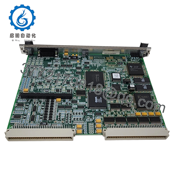
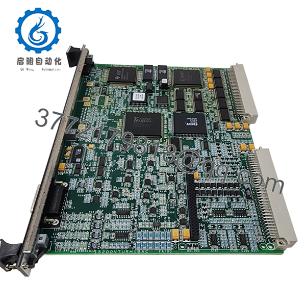
| Model Number | IS200VTURH1B |
| Product Type | Turbine Control Interface Board |
| Platform | GE Mark VI Speedtronic |
| Primary Function | Turbine protection and control interfacing |
| System Compatibility | Mark VI turbine control racks |
| Mounting Method | Rack-mounted PCB assembly |
| Signal Handling | Turbine process and protection signals |
| Communication Interface | Mark VI backplane communication |
| Diagnostic Indicators | Onboard status LEDs |
| Operating Temperature | 0 °C to 60 °C |
| Storage Temperature | −40 °C to +85 °C |
| Humidity Rating | 5% to 95% non-condensing |
| PCB Revision | H1B |
| Compliance Practices | IEC 61131 industrial control standards |
| Packaging | ESD-safe sealed packaging |
4. Product Introduction
The GE IS200VTURH1B is a Mark VI turbine control interface board used in GE Speedtronic gas and steam turbine systems. It handles critical turbine control and protection signal interfacing inside the Mark VI architecture.
Plants typically deploy this board during lifecycle maintenance projects, outage spare replacement, or legacy cabinet restoration work. Many operators continue using Mark VI infrastructure because the installed logic base, field wiring, and turbine permissives remain tightly integrated with existing plant operations.
5. Installation & Configuration Guide
Stage 1: Pre-Installation Preparation (Estimated Time: 10 Minutes)
⚠️ Safety First
- Coordinate with operations before shutdown.
- Place the turbine and associated auxiliaries into a verified safe state.
- Apply lock out/tag out procedures to all cabinet power sources.
- Wait a minimum of 5 minutes for internal DC bus discharge.
Tools Required
- ESD grounding wrist strap
- PH1 screwdriver
- Fluke 115 multimeter or equivalent
- Wire labels and marker
- Smartphone for documentation photos
- Flashlight for cabinet inspection
Data Backup
- Save the running Mark VI configuration and controller backup.
- Record rack location and board slot assignment.
- Photograph:
- Terminal wiring
- Shield grounding
- Jumper settings
- Connector orientation
- Document any custom field modifications.
❗Take photos before disconnecting anything. I still see experienced technicians skip this step during outage pressure, then spend hours tracing one missed terminal.
Stage 2: Removing the Old Module (Estimated Time: 5–10 Minutes)
- Remove cabinet shields or front bezels as required.
- Label every field cable before disconnecting it.
- Disconnect wiring carefully. Do not pry against the PCB.
- Release rack locking tabs or mounting screws.
- Pull the board straight out evenly.
Inspection Checklist
- Check for bent backplane pins
- Look for overheated connectors
- Inspect for dust contamination
- Verify no loose hardware remains in the rack
⚠️ Note
Do not discard the original board until the replacement has completed startup and operational testing successfully.
Stage 3: Installing the New Module (Estimated Time: 10 Minutes)
- Ground yourself with the ESD strap before handling the replacement board.
- Confirm exact model number: IS200VTURH1B.
- Verify PCB revision and connector alignment.
Configuration Clone (Crucial)
- Match all jumper and switch positions from the original module.
- Verify any address or termination settings.
- Compare shield grounding arrangements carefully.
❗This is where many startup delays begin. One misplaced jumper can create intermittent turbine permissive faults that look like a software issue.
Installation Steps
- Insert the board evenly into rack guides.
- Push firmly until the board seats completely.
- Tighten retaining hardware evenly.
- Reconnect field wiring with proper torque control.
Self-Checklist
- Correct board revision
- Jumpers duplicated
- Wiring verified
- Ground shields restored
- Board fully seated
Stage 4: Power-On & Testing (Estimated Time: 15–20 Minutes)
Pre-Power Check
- Use a multimeter to check the 24 V rail for shorts.
- Verify cabinet grounding continuity.
- Confirm no loose conductors remain inside the cabinet.
Power-On Procedure
- Energize the Mark VI rack first.
- Observe onboard LEDs:
- Green RUN = Normal startup
- Red ERR = Fault condition
- Connect the engineering workstation.
- Verify:
- Board recognition
- Hardware diagnostics
- Communication status
- Firmware compatibility
- Restore configuration if necessary.
- Perform dry-run turbine permissive checks before enabling field devices.
⚠️ Troubleshooting Notes
- Solid ERR LED: Suspect firmware incompatibility or backplane communication issue.
- No communication: Verify rack slot assignment and connector seating.
- Intermittent faults: Check shield grounding and terminal torque.
I’ve seen technicians replace three perfectly good boards before discovering one loose shield drain wire causing noise-induced trips.
Technical Pitfalls & Survival Guide
❗ Firmware Revision Mismatch
A newer board revision may not behave correctly with older Mark VI controller firmware.
Before replacement:
- Record firmware revisions
- Verify approved compatibility range
- Coordinate with the controls engineer
I worked one outage where a replacement board introduced startup delays because the newer revision changed diagnostic timing slightly. The controller interpreted it as a failed handshake.
❗ DIP Switch / Jumper Misconfiguration
Factory jumper settings rarely match plant requirements.
Before removal:
- Take close-up photos
- Label anything unclear
- Compare every jumper manually
This is one of the most common causes of post-maintenance comms alarms.
❗ Terminal Block & Wiring Variations
Connector layouts can differ between revisions.
Always verify:
- Pin assignments
- Shield grounding points
- Terminal numbering
Do not wire from memory. Even similar Mark VI boards can differ internally.
❗ Power Supply Loading
Replacement hardware can slightly alter rack loading characteristics.
Verify:
- Backplane current capacity
- Cabinet thermal load
- Available PSU headroom
Leave at least 20% margin on the DC supply.
❗ Electrostatic Discharge (ESD)
Dry winter conditions are brutal on exposed control electronics.
Use:
- Grounded ESD strap
- Anti-static mat
- Proper storage packaging
I once watched a replacement board fail instantly because someone carried it across carpet and installed it bare-handed. The startup window disappeared right there.
Keep these checks in mind and you’ll save yourself 90% of typical rework time.

- IS200VTURH1B
- IS200VTURH1B
6. Frequently Asked Questions (FAQ)
Q1: Can I hot-swap the GE IS200VTURH1B while the cabinet is energized?
No. This board is not intended for hot swapping. Removing or inserting it under power can damage the Mark VI backplane or trigger turbine protection faults. Shut the cabinet down fully first.
Q2: Is the IS200VTURH1B still manufactured by GE?
The Mark VI family is considered legacy equipment. Availability today mainly comes from surplus OEM inventory, decommissioned plant stock, or authorized industrial inventory channels.
Stock availability changes constantly because many utilities still rely on Mark VI systems.
Q3: Is this board new or refurbished?
This listing refers to New Original / New Surplus inventory unless otherwise specified.
That means:
- OEM-manufactured hardware
- No field service history
- Stored inventory stock
Each unit still undergoes inspection and functional verification before shipment.
Q4: Will replacing this board erase my turbine logic?
Normally, no. Primary application logic resides in the Mark VI controllers, not this interface board.
Still, always back up:
- Configuration files
- Controller databases
- Hardware mappings
I’ve seen rushed maintenance jobs create unnecessary downtime because nobody captured the original hardware mapping first.
Q5: What should I verify before ordering?
Check:
- Full model number
- Revision suffix
- Existing firmware revision
- Cabinet slot location
- Wiring compatibility
One missing suffix letter can create connector or firmware mismatches.
Q6: Why are some IS200VTURH1B units priced very differently online?
Traceability and testing standards vary heavily in the surplus automation market.
Lower-cost units may:
- Lack test documentation
- Have unknown storage history
- Be repaired instead of original
Ask for:
- Serial photos
- Functional test reports
- PCB inspection records
- Packaging photos
Q7: What testing is performed before shipment?
Typical QC process includes:
- Visual PCB inspection
- Connector integrity check
- Power-on diagnostics
- Communication verification
- Continuous observation testing
- ESD-safe packaging
Testing is commonly performed using a genuine Mark VI rack or compatible simulation environment. Photos and test videos are available upon request.


