
 WhatsApp: +86 16626708626
 Email:
  Phone: +86 16626708626
Description
3. Key Technical Specifications
| Parameter | Value |
|---|---|
| Manufacturer | GE General Electric |
| Model Number | IS200VVIBH1CAB-W02 |
| Product Family | GE Mark VIe / Speedtronic |
| Product Type | VME Vibration Monitoring Card |
| Primary Application | Turbine vibration and condition monitoring |
| System Compatibility | GE Mark VIe turbine control systems |
| Signal Type Support | Accelerometers and proximity probe inputs |
| Analog Signal Support | 4–20 mA, ±10 V typical |
| Communication Architecture | VME bus interface |
| Input Power | 24 VDC ±10% |
| Mounting Method | Rack / VME slot mounting |
| Operating Temperature | Typically −20 °C to +70 °C cabinet environment |
| PCB Protection | Conformal coated industrial PCB |
| Diagnostic Features | LED diagnostics and fault monitoring |
| Firmware Dependency | Verify compatibility with installed Mark VIe revision |
| Compliance Reference | IEC 61131 industrial control practices |
| Availability | Limited surplus inventory |
| Typical Lead Time | 3–7 business days depending on stock |
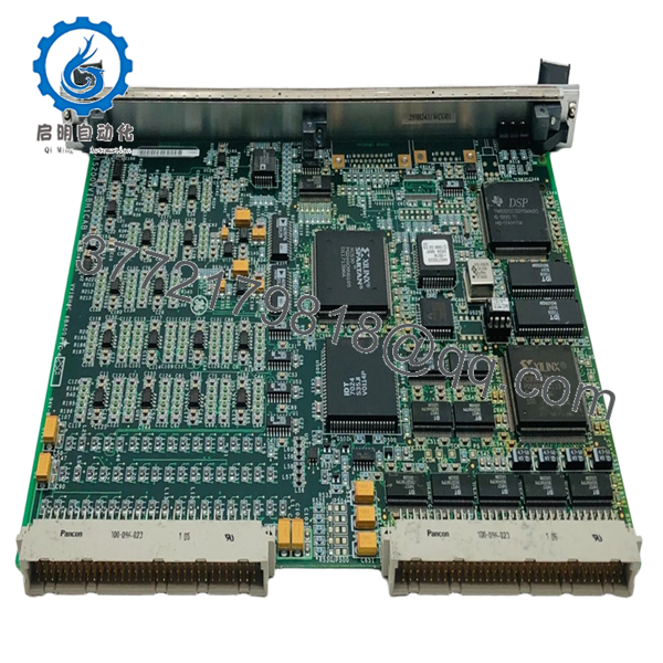
The IS200VVIBH1CAB-W02 is commonly identified as a GE Mark VIe vibration monitoring card used for turbine condition monitoring and vibration signal acquisition within Speedtronic turbine control architectures.
4. Product Introduction
The GE IS200VVIBH1CAB-W02 is a VME-based vibration monitoring module used in GE Mark VIe Speedtronic turbine control systems. The module acquires and processes vibration-related analog signals from proximity probes and accelerometers installed on gas and steam turbines for machine protection and condition monitoring applications.
In field turbine environments, vibration cards like the IS200VVIBH1CAB-W02 are treated as critical protection hardware because unstable or inaccurate vibration feedback can trigger nuisance trips or mask developing bearing failures. Plants maintaining Mark VIe infrastructure often stock spare vibration cards onsite to reduce outage duration during forced maintenance events.
- IS200VVIBH1CAB-W02
- IS200VVIBH1CAB-W02
5. Installation & Configuration Guide
Stage 1: Pre-Installation Preparation (Estimated Time: 10 Minutes)
⚠️ Safety First
- Notify operations and turbine supervision personnel before shutdown.
- Verify the turbine is in a safe shutdown condition.
- Apply lock out/tag out (LOTO) procedures to cabinet power sources.
- Wait a minimum of 5 minutes for cabinet capacitors to discharge fully.
Tools Required
- Grounded ESD wrist strap
- PH1 screwdriver
- Fluke 115 multimeter or equivalent
- Wire labels
- Smartphone for cabinet photos
- Flashlight for rack inspection
Data Backup
- Export vibration monitoring configuration from the Mark VIe engineering workstation.
- Record:
- Rack slot location
- IP/network settings
- Sensor scaling parameters
- Alarm trip thresholds
- Photograph all wiring and jumper positions before removal.
❗ Take photos before disconnecting anything. I’ve watched maintenance teams lose half a shift trying to recover probe channel assignments after someone assumed “the labels were obvious.”
Stage 2: Removing the Old Module (Estimated Time: 5–10 Minutes)
- Open cabinet covers carefully.
- Verify all associated rack power is isolated.
- Label vibration probe wiring and connectors.
- Release card retention hardware.
- Pull the module straight out evenly from the VME rack.
- Inspect the backplane for:
- Bent pins
- Oxidation
- Dust contamination
- Heat discoloration
⚠️ Important Note
Keep the removed module available during commissioning. It provides valuable reference information for firmware revision checks and jumper configuration.
Stage 3: Installing the New Module (Estimated Time: 10–15 Minutes)
Installation Steps
- Wear grounded ESD protection before handling the module.
- Verify the exact replacement model number:
- IS200VVIBH1CAB-W02
- Compare hardware revision labels carefully.
- Configuration Clone (Crucial):
- Replicate all jumper and DIP switch settings exactly
- Verify probe channel assignments
- Confirm termination and grounding settings
- Align the card evenly with the VME rack guides.
- Insert firmly until fully seated.
- Tighten retention hardware securely.
- Reconnect all sensor wiring and communication cables.
Self-Checklist
- Model verified
- Firmware revision checked
- DIP switches matched
- Card seated fully
- Probe wiring secured
❗ Incomplete seating is one of the nastiest intermittent faults on VME racks. The card powers partially, LEDs look normal, and the system throws random vibration communication alarms for hours.
Stage 4: Power-On & Testing (Estimated Time: 15–20 Minutes)
Pre-Power Check
- Verify no short exists on the 24 VDC rail.
- Confirm cabinet grounding continuity.
- Check shield grounding on vibration probe cables.
- Inspect for loose hardware inside the rack.
Power-On Steps
- Energize the rack before enabling field devices.
- Observe startup LEDs and diagnostic indicators.
- Connect the Mark VIe engineering workstation.
- Verify the module appears correctly in the hardware tree.
- Confirm firmware revision compatibility.
- Validate probe signal values and vibration trends.
- Perform dry-run alarm testing before turbine startup.
⚠️ Troubleshooting Note
If the module reports unstable vibration values immediately after startup:
- Check shield grounding first
- Verify probe polarity and gap voltage
- Recheck firmware compatibility
- Inspect VME backplane seating
- Verify sensor scaling parameters
I’ve seen engineers replace perfectly good probes because a replacement vibration card shipped with a newer firmware revision that handled filtering slightly differently. The machine protection logic started flagging false vibration spikes during startup ramps.
Quality Control & Testing Procedure
1. Inbound Inspection & Traceability
Each IS200VVIBH1CAB-W02 module undergoes:
- OEM label verification
- Serial number traceability inspection
- Anti-counterfeit inspection
- PCB inspection for corrosion, repaired traces, solder rework, and UV yellowing
- Connector and VME edge-contact inspection
2. Live Functional Testing
Testing is performed using GE Mark VIe-compatible hardware whenever available.
Procedures include:
- Controlled power-up testing
- LED startup verification
- VME communication testing
- Analog vibration signal simulation
- Probe signal acquisition testing
- Continuous energized runtime testing exceeding 24 hours with thermal monitoring
Test videos and diagnostic screenshots are available upon request.
3. Electrical Parameter Testing
- 500 V insulation resistance testing (>10 MΩ target)
- Ground continuity verification
- DC rail stability measurement
- Analog signal integrity checks using calibrated Fluke instruments
4. Firmware & Configuration Verification
- Firmware revision documentation
- DIP switch and jumper recording
- Hardware revision verification
5. Final QC & Packaging
- QC technician sign-off
- Anti-static ESD bagging
- Shock-resistant bubble wrap protection
- Heavy-duty corrugated export carton
- QC Passed labeling with inspection date
6. Frequently Asked Questions (FAQ)
Q1: Can the IS200VVIBH1CAB-W02 be hot-swapped?
No.
This module participates directly in turbine vibration protection and monitoring. Pulling it live can destabilize the Mark VIe rack or generate false trip conditions.
Power the cabinet down completely before replacement.
Q2: What does this module actually monitor?
The IS200VVIBH1CAB-W02 monitors turbine vibration signals from accelerometers and proximity probes installed on rotating equipment. It processes vibration data used for machine protection, condition monitoring, and alarm generation.
Q3: Is this part still manufactured by GE?
This is considered a legacy turbine control component.
Most currently available inventory comes from:
- New surplus stock
- Strategic plant spare inventories
- Professionally tested refurbishment channels
Availability fluctuates constantly because many operating turbines still rely on these systems.
Q4: Why does firmware revision matter so much on vibration cards?
Because vibration processing algorithms can change between revisions.
I’ve seen situations where a replacement card installed successfully but generated nuisance vibration alarms during acceleration ramps because the filtering behavior differed slightly from the original hardware revision.
Always document firmware before removal.
Q5: What is the most common installation mistake?
❗ Incorrect probe grounding and shielding.
Technicians often reconnect shields improperly after maintenance. The result is noisy vibration readings, unstable trends, and intermittent alarms that look like bearing damage.
Check grounding carefully before blaming the probes.
Q6: Will replacing this module erase turbine control logic?
Normally no.
The vibration card processes monitoring signals, but the primary turbine application logic typically resides elsewhere within the Mark VIe architecture. Still, always back up configuration and trip settings before maintenance work.
Q7: Why are some IS200VVIBH1CAB-W02 modules much cheaper than others?
Usually because of condition and testing differences.
Pricing depends on:
- New surplus versus repaired inventory
- Live rack testing status
- Firmware revision
- Connector condition
- Traceability records
- Cosmetic condition
If a supplier cannot provide actual test reports, photos, or revision documentation, proceed carefully.
Keep these checks in mind and you’ll avoid most of the painful troubleshooting sessions that happen during turbine vibration system maintenance.


