
 WhatsApp: +86 16626708626
 Email:
  Phone: +86 16626708626
Description
3. Key Technical Specifications
| Parameter | Value |
|---|---|
| Manufacturer | GE General Electric |
| Model Number | IS2020LVPSG1AE |
| Functional Acronym | LVPS |
| Product Type | VME Rack Power Supply Module |
| Platform | GE Mark VI Speedtronic |
| Input Voltage | 24 VDC |
| Output Power Rating | 300 W to 400 W depending on configuration |
| PSA Outputs | Up to 5 x +28 V PSA outputs |
| Remote Outputs | Up to 3 x +28 V remote outputs |
| Redundancy Support | Not supported on G1AE revision |
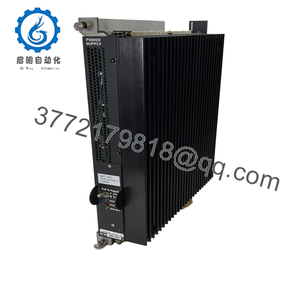
| Status Indicators | Available, Normal, Fault LEDs |
| Mounting Method | VME rack-mounted |
| Operating Temperature | 0 °C to 60 °C |
| Storage Temperature | −40 °C to +85 °C |
| PCB Coating | Standard industrial coating |
| System Compatibility | GE Mark VI turbine control systems |
| Packaging | ESD-safe sealed export packaging |
4. Product Introduction
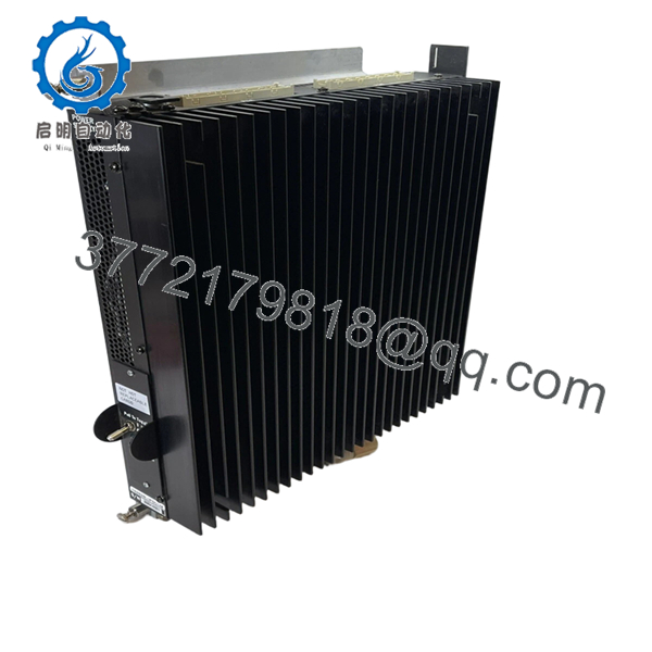
The GE IS2020LVPSG1AE is a low-voltage VME rack power supply module used in GE Mark VI Speedtronic turbine control systems. It distributes regulated DC power to Mark VI control and interface boards inside turbine control cabinets.
In field service work, this module is commonly replaced during lifecycle extension projects where plants continue operating existing Mark VI infrastructure rather than migrating immediately to Mark VIe. Engineers typically select this unit when maintaining original cabinet layouts, VME rack compatibility, and existing turbine control wiring.

- IS2020LVPSG1AE
- IS2020LVPSG1AE
5. Installation & Configuration Guide
Stage 1: Pre-Installation Preparation (Estimated Time: 10–15 Minutes)
⚠️ Safety First
- Coordinate the shutdown with operations and turbine controls personnel.
- Bring the turbine and auxiliaries into a verified safe state.
- Lock out/tag out all cabinet power sources.
- Wait at least 5 minutes for DC bus discharge before touching the rack.
Tools Required
- Grounded ESD wrist strap
- PH1 screwdriver
- Fluke 115 multimeter or equivalent
- Wire labels
- Smartphone for cabinet photos
- Flashlight for rack inspection
Data Backup
- Export the Mark VI configuration and cabinet diagnostics.
- Record rack slot position and harness routing.
- Photograph:
- PSA and PSB harness connections
- Grounding points
- Connector orientation
- Rack labeling
- Document the installed firmware baseline and power supply revision.
❗Do not skip the wiring photos. I’ve seen outage crews reconnect PSA and PSB harnesses backward after a midnight swap. The rack stayed dark for six hours while everyone blamed the replacement power supply.
Stage 2: Removing the Old Module (Estimated Time: 5–10 Minutes)
- Remove cabinet covers and protective barriers carefully.
- Label all harnesses before disconnecting them.
- Disconnect PSA and PSB connectors evenly without twisting the PCB.
- Release retaining screws or mounting tabs.
- Pull the module straight out from the VME rack.
Inspection Checklist
- Inspect backplane connectors for bent pins
- Check for overheated terminals
- Verify no dust buildup inside airflow channels
- Look for capacitor swelling or PCB discoloration
⚠️ Note
Keep the original power supply available until startup and load testing are complete successfully.
Stage 3: Installing the New Module (Estimated Time: 10 Minutes)
- Wear the ESD wrist strap before opening the anti-static packaging.
- Verify exact model number: IS2020LVPSG1AE.
- Confirm harness connector alignment and revision markings.
Configuration Clone (Crucial)
- Match all jumper and configuration settings exactly.
- Verify PSA and PSB harness routing.
- Confirm grounding straps and shield terminations are restored properly.
❗This is where many rack failures start. Someone assumes all LVPS revisions wire the same, skips the verification step, and suddenly the VME rack loses half its outputs during startup.
Installation Steps
- Align the module carefully with rack guides.
- Insert evenly until fully seated.
- Tighten retaining hardware securely.
- Reconnect all harnesses using proper torque control.
Self-Checklist
- Correct model verified
- Harnesses matched properly
- Grounding restored
- Module fully seated
- Retaining tabs secured
Stage 4: Power-On & Testing (Estimated Time: 20 Minutes)
Pre-Power Check
- Use a multimeter to verify no short exists on the 24 VDC rail.
- Check cabinet grounding continuity.
- Confirm all connectors are fully seated.
Power-On Procedure
- Energize the VME rack only.
- Observe status LEDs:
- Available LED = Input power present
- Normal LED = Output healthy
- Fault LED = Power supply problem detected
- Connect the engineering workstation.
- Verify:
- Rack initialization
- Power rail stability
- Board communication
- No undervoltage alarms
- Restore field device power after rack diagnostics pass.
- Perform dry-run I/O testing before returning the turbine to service.
⚠️ Troubleshooting Notes
- Fault LED illuminated: Suspect overloaded power rail or incorrect harness connection.
- Rack instability: Check total VME rack power consumption.
- No startup response: Verify 24 VDC feed polarity and backplane seating.
I’ve seen technicians replace three controller boards before realizing the actual problem was one unstable LVPS output sagging under load.
Technical Pitfalls & Survival Guide
❗ Firmware & Hardware Revision Mismatch
Different LVPS revisions can behave differently with older Mark VI cabinet configurations.
Before replacement:
- Record hardware revision
- Verify compatible cabinet BOM
- Confirm approved firmware baseline
One plant I worked with installed a newer revision without checking compatibility. The rack booted, then intermittently dropped communications under full I/O load.
❗ PSA / PSB Harness Misconfiguration
This happens constantly during rushed outages.
Before disconnecting:
- Label every harness
- Photograph connector orientation
- Verify pin alignment manually
A reversed harness can damage rack power distribution instantly.
❗ Terminal & Connector Differences
GE revised some connector mappings between production generations.
Always verify:
- Connector keys
- Harness routing
- Ground locations
- Pin assignments
Never assume based on physical appearance alone.
❗ Power Draw Calculations
This module feeds multiple rack subsystems simultaneously.
Verify:
- Total rack power consumption
- Cabinet thermal load
- Available DC supply capacity
Leave at least a 20% margin on the cabinet power supply.
For example, a partially loaded Mark VI rack may behave normally during idle diagnostics, then collapse under startup load when all I/O channels energize simultaneously.
❗ Electrostatic Discharge (ESD)
Power supply boards are extremely sensitive during handling.
Use:
- Grounded ESD strap
- Anti-static work surface
- ESD-safe storage bags
I once watched a contractor carry one across carpet during winter shutdown season. Installed it, powered the rack, and immediately lost the output rail.
Keep these checks in mind and you’ll save yourself 90% of typical rework time.
6. Frequently Asked Questions (FAQ)
Q1: Can I hot-swap the GE IS2020LVPSG1AE?
No. This module powers the VME rack directly. Removing it under power can collapse the rack power rail and potentially damage connected boards. Always isolate cabinet power first.
Q2: Is the IS2020LVPSG1AE obsolete?
Yes. The Mark VI platform is considered legacy equipment. Many units now come from surplus OEM inventory or decommissioned plant stock. Availability changes frequently because utilities still maintain large installed Mark VI fleets.
Q3: Is this unit genuinely new or refurbished?
This inventory is classified as New Original / New Surplus unless otherwise specified.
Typical verification includes:
- OEM label inspection
- Serial number checks
- PCB visual inspection
- Power-on diagnostics
- Connector integrity testing
Inspection photos and test records are available upon request.
Q4: Why do some datasheets list 300 W while others show 400 W?
This confusion appears frequently in surplus documentation for the IS2020LVPSG1AE family. Different revisions and harness configurations are documented differently across industrial inventories. Always verify the exact installed revision and cabinet requirements before ordering.
Q5: Does this module support redundant operation?
The G1AE revision generally does not support full redundant operation. If the application requires redundancy, verify whether the cabinet design expects a redundant-capable LVPS variant before installation.
Q6: Why is surplus pricing so inconsistent?
Traceability and testing standards vary heavily in the surplus controls market.
Lower-priced units may:
- Lack load testing
- Have unknown storage history
- Be repaired assemblies
- Include no documentation
Ask suppliers for:
- Test reports
- Rack test photos
- Serial verification
- Packaging photos
Q7: What testing is performed before shipment?
Typical QC procedures include:
- Inbound Inspection & Traceability
- OEM label verification
- Serial number inspection
- Connector and PCB inspection
- Anti-counterfeit checks
- Functional Testing
- Installed into a genuine Mark VI VME rack
- Power-on verification
- LED diagnostics
- Output rail validation
- 24-hour observation testing where applicable
- Electrical Testing
- Ground continuity verification
- Insulation resistance testing
- Voltage rail stability checks
- Final QC & Packaging
- QC sign-off
- ESD bag sealing
- Heavy-duty export carton packaging
- QC date labeling
Photos and test videos are available upon request.


