
 WhatsApp: +86 16626708626
 Email:
  Phone: +86 16626708626
Description
3. Key Technical Specifications
| Parameter | Value |
|---|---|
| Manufacturer | GE General Electric |
| Model Number | IS2020RKPSG3A |
| Functional Acronym | RKPS |
| Product Type | VME Rack Power Supply |
| Platform | GE Mark VI Speedtronic |
| Input Voltage | 125 VDC |
| Output Power Rating | 400 W |
| Supported Rack Type | VME control and interface racks |
| Output Rails | +5 VDC, +12 VDC, +15 VDC, +28 VDC |
| Optional Output | 335 VDC flame detector supply |
| PSA Outputs | Five +28 V PSA outputs |
| Remote Output | One remote +28 V PSA output |
| Status Indicators | Green, Yellow, Red LEDs |
| User Controls | Front-panel toggle/reset switch |
| Mounting Method | Side-mounted on VME rack |
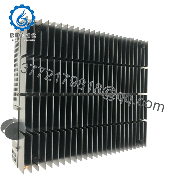
| Cooling Method | Passive heatsink fins |
| Operating Temperature | 0 °C to 60 °C |
| Storage Temperature | −40 °C to +85 °C |
| PCB Coating | Standard industrial coating |
| System Architecture | Simplex or TMR Mark VI systems |
4. Product Introduction
The GE IS2020RKPSG3A is a VME rack power supply module used in GE Mark VI Speedtronic turbine control systems. It provides regulated DC power to Mark VI control racks, interface boards, and associated system electronics in gas and steam turbine applications.
In field installations, this module is commonly used in both Simplex and TMR Mark VI architectures where stable rack power and fault monitoring are critical. Many plants continue maintaining these power supplies during outage cycles because replacing the complete Mark VI infrastructure often requires major cabinet redesign and extended commissioning time.

- IS2020RKPSG3A
5. Installation & Configuration Guide
Stage 1: Pre-Installation Preparation (Estimated Time: 10–15 Minutes)
⚠️ Safety First
- Coordinate the shutdown with turbine operations and controls personnel.
- Bring the turbine and auxiliaries into a confirmed safe state.
- Apply lock out/tag out procedures to all cabinet feeds.
- Wait at least 5 minutes for DC bus discharge before touching the rack.
Tools Required
- Grounded ESD wrist strap
- PH1 screwdriver
- Fluke 115 multimeter or equivalent
- Wire labels
- Smartphone for cabinet documentation
- Flashlight for rack inspection
Data Backup
- Export Mark VI diagnostics and controller configuration.
- Record the exact rack location and power harness routing.
- Photograph:
- PSA/PSB connectors
- Grounding straps
- Jumper positions
- Front-panel switch positions
- Document cabinet input voltage configuration.
❗This is where outage mistakes start. I’ve seen technicians assume every RKPS variant is wired identically, then spend half a shift tracing why the rack won’t initialize after startup.
Stage 2: Removing the Old Module (Estimated Time: 5–10 Minutes)
- Remove cabinet covers carefully.
- Label every PSA and PSB harness before disconnecting.
- Disconnect the lower DC input and output connectors evenly.
- Release retaining screws and mounting hardware.
- Pull the module straight out from the rack bracket.
Inspection Checklist
- Check backplane connectors for bent pins
- Inspect heatsink fins for debris buildup
- Look for capacitor discoloration or swelling
- Verify no loose hardware remains inside the cabinet
⚠️ Note
Keep the original module available until the replacement passes full startup and load testing.
Stage 3: Installing the New Module (Estimated Time: 10 Minutes)
- Wear the ESD strap before opening the anti-static packaging.
- Verify exact model number: IS2020RKPSG3A.
- Confirm the replacement matches the cabinet voltage requirements.
Configuration Clone (Crucial)
- Match all jumper and harness configurations exactly.
- Verify PSA and PSB cable orientation carefully.
- Confirm grounding straps are restored properly.
❗One reversed PSA harness can take down half the VME rack power distribution. I’ve watched experienced maintenance crews lose hours troubleshooting what turned out to be one connector shifted by a single position.
Installation Steps
- Align the module with the rack bracket and guides.
- Insert evenly until fully seated.
- Tighten retaining hardware securely.
- Reconnect all power and status connectors.
Self-Checklist
- Model verified
- Input voltage confirmed
- Harnesses connected correctly
- Grounding restored
- Module fully seated
Stage 4: Power-On & Testing (Estimated Time: 20 Minutes)
Pre-Power Check
- Use a multimeter to verify no shorts on the DC rail.
- Confirm cabinet grounding continuity.
- Verify PSA and PSB connectors are seated fully.
Power-On Procedure
- Energize the VME rack only.
- Observe LED indicators:
- Yellow LED = Input power present
- Green LED = Normal operation
- Red LED = Fault condition
- Connect the engineering workstation.
- Verify:
- Rack startup
- Stable voltage rails
- No undervoltage alarms
- Proper board communication
- Restore field device power after diagnostics pass.
- Perform dry-run I/O and rack communication checks.
⚠️ Troubleshooting Notes
- Red fault LED active: Check output overload or undervoltage conditions.
- Rack instability: Verify total rack power consumption.
- No startup response: Check 125 VDC input polarity and connector seating.
I’ve seen plants replace perfectly good controllers when the actual issue was a weak RKPS output collapsing under startup load.
Technical Pitfalls & Survival Guide
❗ Firmware & Hardware Revision Mismatch
Different RKPS revisions have different electrical behaviors and connector expectations.
Before replacement:
- Verify cabinet BOM
- Record hardware revision
- Confirm approved Mark VI configuration
One site installed the wrong RKPS revision during a turbine outage and spent nearly a full day chasing intermittent rack resets.
❗ PSA / PSB Harness Errors
This happens constantly during rushed maintenance windows.
Before disconnecting:
- Label every connector
- Photograph orientation clearly
- Verify harness routing manually
Do not trust memory under outage pressure.
❗ Terminal & Connector Differences
GE revised connector arrangements between RKPS generations.
Always verify:
- Connector keys
- Pin assignments
- Grounding locations
- External peripheral wiring
Never wire solely based on physical fit.
❗ Power Draw Calculations
The RKPS feeds multiple VME rack sections simultaneously.
Verify:
- Total rack load
- Cabinet airflow
- Available DC supply margin
Leave at least 20% headroom on the upstream DC source.
A rack may pass idle diagnostics but fail during startup when every I/O rail energizes simultaneously.
❗ Electrostatic Discharge (ESD)
These power modules are highly vulnerable during handling.
Use:
- Grounded wrist strap
- ESD-safe work surface
- Anti-static storage packaging
I once watched a replacement RKPS fail immediately after installation because it was unpacked on a dry concrete floor without grounding precautions.
Keep these checks in mind and you’ll save yourself 90% of typical rework time.
6. Frequently Asked Questions (FAQ)
Q1: Can I hot-swap the GE IS2020RKPSG3A?
No. This module powers the Mark VI VME rack directly. Removing it under power can collapse rack voltage rails and potentially damage connected control boards. Shut down cabinet power first.
Q2: Is the IS2020RKPSG3A obsolete?
Yes. The Mark VI family is considered legacy GE turbine control hardware. Most available inventory now comes from surplus OEM stock or decommissioned plant systems.
Q3: What input voltage does this RKPS version require?
The IS2020RKPSG3A variant is generally designed for 125 VDC input applications. GE produced several RKPS versions with different voltage requirements, so always verify the installed cabinet specification before replacement.
Q4: Does this module provide the 335 VDC flame detector output?
Some RKPS configurations support the optional 335 VDC output used for TRPG flame detector circuits. Verify whether your cabinet wiring and installed hardware revision require this feature before ordering.
Q5: Is this unit genuinely new or refurbished?
This inventory is classified as New Original / New Surplus unless otherwise specified.
Typical verification includes:
- OEM label inspection
- Serial number checks
- PCB visual inspection
- Power-on diagnostics
- Connector inspection
- Load observation testing
Test photos and inspection records are available upon request.
Q6: Why do prices vary so much between suppliers?
Testing standards and traceability vary heavily in the surplus controls market.
Lower-cost units may:
- Skip load testing
- Have unknown storage conditions
- Include repaired assemblies
- Lack serial traceability
Ask suppliers for:
- Test reports
- Rack startup photos
- Serial verification
- Packaging documentation
Q7: What testing is performed before shipment?
Typical QC procedures include:
- Inbound Inspection & Traceability
- OEM label verification
- Serial inspection
- Anti-counterfeit checks
- Connector and PCB inspection
- Functional Testing
- Installed into a genuine Mark VI VME rack
- Power-on diagnostics
- Voltage rail validation
- LED status verification
- Continuous observation testing
- Electrical Testing
- Ground continuity checks
- Insulation resistance testing
- DC output stability verification
- Final QC & Packaging
- QC sign-off
- ESD bag sealing
- Heavy-duty export carton packaging
- QC date labeling
Photos and startup test videos are available upon request.


