
 WhatsApp: +86 16626708626
 Email:
  Phone: +86 16626708626
Description
3. Key Technical Specifications
| Parameter | Value |
|---|---|
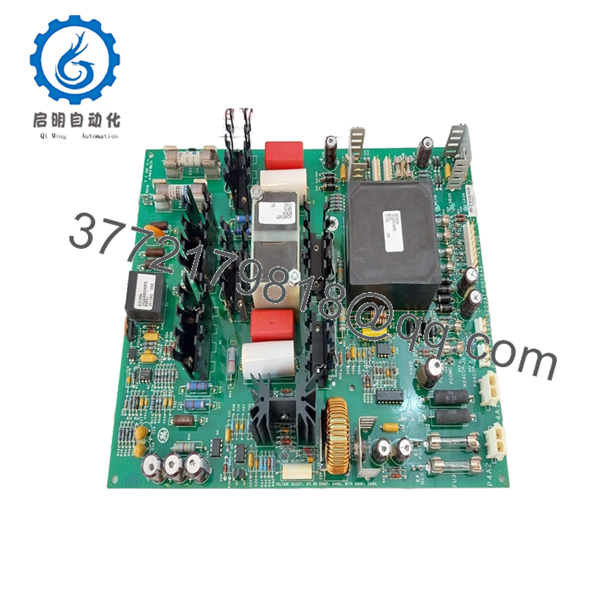
| Model Number | IS210AEPSG1B |
| Manufacturer | GE Energy |
| Product Category | Alternative Energy Power Supply Module |
| Functional Acronym | AEPS |
| Platform | GE Mark VIe Wind Turbine Control |
| Primary Function | Regulated power conversion and conditioning |
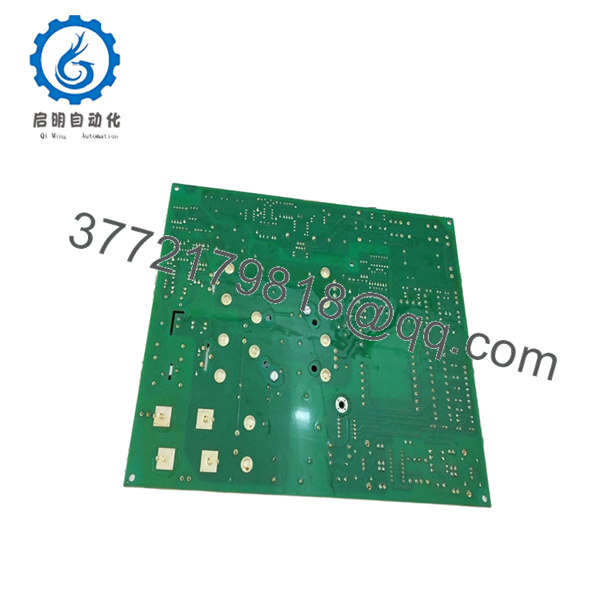
| PCB Protection | Conformal coating |
| Functional Revision | Revision B |
| Architecture Support | Redundant power configurations |
| Installation Type | Rack / cabinet mounted PCB |
| Approximate Weight | 1.66 kg |
| Application | Wind turbine control and auxiliary power distribution |
| Product Lifecycle | Limited availability / surplus market |
The AEPS acronym identifies the board as an Alternative Energy Power Supply module used within GE wind turbine control systems. Hardware documentation available online remains limited, so some field information comes from part-number analysis and component inspection records.
4. Product Introduction
GE IS210AEPSG1B is an Alternative Energy Power Supply module used in the GE Mark VIe Wind Turbine Control platform. The board provides conditioned and regulated power for control electronics and auxiliary circuits supporting wind turbine operation and associated cabinet functions.
In field deployments, power modules create strange symptoms when they begin failing. I have seen unstable voltage rails generate communication alarms, intermittent sensor faults, and nuisance trips that initially looked unrelated. The problem often gets blamed on controllers first, while the power supply quietly causes the issue in the background. Redundant power configuration matters on critical assets.
5. Installation & Configuration Guide
Stage 1: Pre-Installation Preparation (Estimated: 10 minutes)
⚠️ Safety First: Notify operations of downtime. Verify the turbine or process equipment has reached a safe condition. Apply lockout/tagout procedures. Remove control power and wait 5 minutes minimum for stored energy discharge.
Tools Required:
- ESD wrist strap
- PH1 screwdriver
- Fluke 115 multimeter
- Wire labels
- Smartphone camera
- ESD mat
Data Backup
- Export current control configuration.
- Record active alarms.
- Photograph all connector locations.
- Photograph DIP switches and hardware settings.
- Record revision labels.
I’ve walked into outages where someone said, “I know where these connectors go.” Forty-five minutes later, four people were tracing cables.
Stage 2: Removing the Old Module (Estimated: 5 minutes)
- Remove cabinet access panels.
- Label and disconnect all field connections.
- Release retaining clips or mounting hardware.
- Pull module straight outward.
- Inspect connector surfaces and backplane pins.
⚠️ Do not rock the board side-to-side.
Bent backplane pins create problems far bigger than the original failure.
⚠️ Keep the old module until the replacement operates correctly.
Stage 3: Installing the New Module (Estimated: 10 minutes)
- Connect ESD protection first.
- Verify exact part number: IS210AEPSG1B
- Configuration Clone (Crucial): Replicate jumper settings and configuration points exactly from photographs.
- Install module and verify full seating.
- Reconnect all wiring.
Self-Checklist:
- Exact model confirmed
- Wiring secure
- Connectors seated
- Hardware locked
- ESD procedures followed
⚠️ This is the most common rookie mistake, but it happens constantly. Take a picture before you pull it. I can’t stress this enough.
Stage 4: Power-On & Testing (Estimated: 10 minutes)
Pre-Power Check
Use a Fluke meter and verify no short exists on DC supply rails.
Power sequence:
- Apply cabinet power only.
- Observe startup indicators.
- Verify regulated output voltages.
- Confirm controller communication.
- Run dry I/O tests.
⚠️ Troubleshooting Note: Immediate communication faults after replacement frequently indicate a configuration or revision issue before actual hardware failure.
I have seen technicians replace three good boards before discovering one configuration mismatch.
Technical Pitfall & Survival Guide
❗ Firmware Revision Mismatch
Issue: Different board revisions occasionally behave differently in mixed systems.
Avoidance: Record revision information before removal.
I’ve seen maintenance teams lose two days chasing communication alarms caused by revision differences. Firmware jumps matter.
❗ DIP Switch / Jumper Misconfiguration
Issue: Default settings rarely match actual plant configuration.
Avoidance: Photograph every setting before removal.
Take pictures. Every outage. No exceptions.
❗ Terminal Block / Wiring Incompatibility
Issue: Similar part numbers can hide different connector layouts.
Avoidance: Compare drawings and physical hardware.
Never wire from memory.
❗ Power Draw Specifications
Issue: Replacement hardware can increase cabinet load.
Avoidance: Keep at least 20% spare capacity on supply calculations.
Power margin disappears faster than expected once cabinets fill with I/O and communication hardware.
❗ Electrostatic Discharge (ESD)
Issue: Static damage before startup.
Avoidance: Use grounded wrist straps and ESD mats.
I watched an engineer unpack a replacement board during winter without a wrist strap. Powered on. Immediate smoke. End of shift.
Keep these checks in mind and you’ll save yourself 90% of typical rework time.
- IS210AEPSG1B
- IS210AEPSG1B
6. Frequently Asked Questions (FAQ)
Q1: Can I hot-swap this module?
No. Do not assume hot-swap capability.
Some third-party descriptions mention online replacement under redundant configurations, but I would verify your exact cabinet architecture and OEM documentation before attempting it. One wrong assumption can trip an operating turbine.
Q2: Is GE IS210AEPSG1B obsolete?
Effectively yes.
OEM documentation and active supply channels are limited. Most inventory now comes from surplus stock and secondary channels.
Q3: Is this genuinely new?
Usually “New Original” means unused surplus inventory stored in industrial warehouses.
Factory packaging may not remain intact after years in storage. Request serial photos and inspection records.
Q4: What is the direct replacement if inventory becomes unavailable?
Verify exact revision compatibility first.
IS210 variants can appear interchangeable on paper while hiding hardware differences. Match suffixes and revision letters carefully.
Q5: Will I lose programming if I replace this module?
Normally no.
This is a power supply module. Primary logic resides elsewhere in the control architecture.
Still back up configurations before touching anything.
Q6: Why is pricing lower than historical OEM pricing?
Production volume is limited and inventory mostly comes from surplus channels.
Current pricing depends on testing history, revision level, and condition rather than historical GE pricing. Inventory availability shifts constantly.
Q7: How do you verify surplus inventory quality?
Our SOP follows a documented inspection sequence:
- OEM packing and serial verification
- Counterfeit checks and traceability review
- Visual inspection for corrosion and rework marks
- Functional testing on GE-compatible hardware where available
- Communication checks
- 500 V Megger insulation test (>10 MΩ)
- Revision documentation and photo archive
- QC sign-off and ESD packaging
We use Fluke instrumentation and generate test records.
Test videos and photos are available upon request.


