
 WhatsApp: +86 16626708626
 Email:
  Phone: +86 16626708626
Description
3. Key Technical Specifications
| Parameter | Specification Value |
| Processor Type | Intel 300 MHz Celeron |
| Volatile Memory | 32 MB or 64 MB SDRAM |
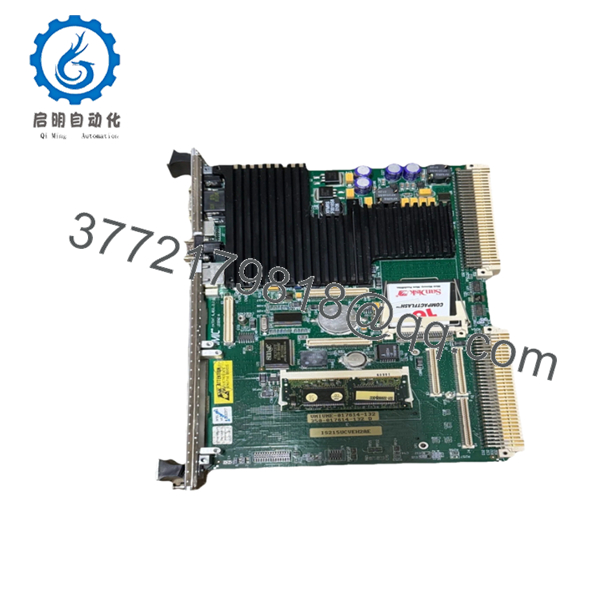
| Non-Volatile Storage | 128 MB Compact Flash |
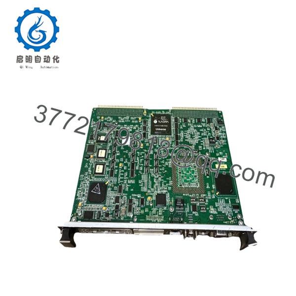
| Form Factor | Single-slot 6U VMEbus |
| Communication Ports | 2 x 10/100 Base-T Ethernet, 2 x COM Ports (RS-232/485) |
| Operating System | QNX Real-Time OS |
| Backplane Interface | VME64 Standard |
| Input Voltage | +5 VDC, +12 VDC, −12 VDC (via VME backplane) |
| Operating Temperature | 0 to +50 °C (+32 to +122 °F) |
| Relative Humidity | 5% to 95% non-condensing |
4. Product Introduction & Supply Chain Strategy
The GE IS215UCVEH2AE is a high-performance VME controller board that serves as the central processing brain for GE Mark VI Speedtronic turbine control systems. Operating on a 300 MHz Intel architecture running a real-time QNX operating system, this module executes complex control algorithms, handles high-speed analog and digital I/O processing, and manages dual-redundant Ethernet communications. It is primarily deployed in utility-scale gas and steam turbine operations, power generation facilities, and heavy industrial process plants where continuous uptime is an operational mandate.
Because GE has officially designated the Mark VI series as legacy hardware, securing this module as a New Surplus unit is a critical risk-mitigation strategy. Relying on refurbished components introduces unpredictable failure vectors due to aged capacitors and hidden thermal stress on the multi-layer circuit board. Acquiring factory-sealed inventory eliminates the threat of secondary failures, lowers the Total Cost of Ownership (TCO) across the lifecycle of the turbine, and provides immediate buffer stock to protect against catastrophic plant stock-outs during unexpected outages.

- IS215UCVEH2AE
- IS215UCVEH2AE
5. Installation & Configuration Guide
Stage 1: Pre-Installation (Prep & Safety)
- Execute strict lock-out/tag-out (LOTO) protocols on the turbine control panel power distribution network.
- Confirm that the 24 VDC auxiliary power supply feeding the VME rack is completely isolated.
- Put on a calibrated, grounded ESD wrist strap and connect it to an unpainted section of the system enclosure frame.
- Document the exact model suffix, hardware revision letters, and configuration jumper positions of the existing card. Take high-resolution photos of all onboard component markings for verification.
Stage 2: Removal
- Disconnect all external Ethernet and serial communication cables from the front faceplate, labeling each cable with its respective port destination.
- Loosen the upper and lower captive retaining screws on the module faceplate using a standard screwdriver.
- Grasp the injector/ejector handles located at the top and bottom of the card, then simultaneously press them outward to unseat the board connectors from the VME64 backplane.
- Slide the module smoothly straight out of the rack chassis along the card guides, ensuring you do not touch any onboard surface-mount components. Place it immediately inside an ESD-safe protective shielding bag.
Stage 3: Installation (Clone & Seat)
- Remove the new surplus IS215UCVEH2AE module from its sealed anti-static packaging.
- Compare the physical hardware configuration, orientation of jumper blocks, and microswitch positions against the original unit. Adjust the settings on the new board to mirror the original configuration exactly.
- Align the module with the designated slot guides inside the VME chassis.
- Slide the card firmly into the rack until the injector/ejector handles contact the chassis rails. Pivot the handles inward to fully engage and seat the backplane pins into the socket assembly, then hand-tighten the front panel captive screws.
Stage 4: Power-On & Testing
- Reconnect all communication interfaces and network cables to the front panel interfaces.
- Measure the primary 24 VDC bus and individual VME backplane power rails to verify that no electrical shorts are present.
- Energize the rack power source and monitor the diagnostic LEDs on the faceplate during the power-on self-test (POST).
- Verify that the green RUN indicator illuminates steadily and the red FAULT or ERR indicator remains completely dark. Connect your engineering workstation via ToolboxST software to download the control application logic and verify active communication handshakes.
6. Firmware/Software Versions & Upgrade Notes
The IS215UCVEH2AE requires a precise firmware baseline matched to the exact major revision of the platform software configuration. This controller typically deploys with native support for the QNX real-time kernel, matching specific GE Toolbox or ToolboxST configuration baselines. It is imperative to check the version of the flash-resident bootloader code before initializing online system synchronization.
Upgrading or downgrading firmware during an emergency hardware replacement carries high execution risks. A sudden firmware version jump can break communication compatibility with downstream I/O termination boards, trigger protocol timeout flags, or prevent the application code from compiling properly. If the replacement module contains a newer firmware version than the existing control network architecture dictates, you must roll back the board firmware to the plant baseline version using an authorized card reader or isolated engineering workstation before placing the unit into active service.
7. Frequently Asked Questions (FAQ)
Q: Why is this New Surplus module priced higher than a refurbished alternative, yet lower than the original OEM list price?
A: This pricing reflects the premium cost of sourcing genuine, unused inventory from verified industrial channels. Refurbished boards are typically repaired or pulled from decommissioned plants, leaving them with high component fatigue. This New Surplus board represents unpowered, zero-hour inventory that delivers OEM-level dependability without the inflated list pricing or extended delivery lead times associated with original factory orders.
Q: Are these units truly brand new, or are they just cleaned up?
A: These are authentic New Surplus components. They have never been placed into active service, never installed on a live chassis, and have zero operational wear. They are original OEM production units preserved in factory-sealed or ESD-safe packaging and are opened solely for our inbound optical and electrical quality inspections.
Q: What is the current lifespan expectation and obsolescence status of the IS215UCVEH2AE?
A: General Electric has classified the Mark VI series as a legacy platform. This means finding replacement parts through traditional channels is increasingly difficult. By deploying a New Surplus module instead of a worn out, used card, you gain an expected operational life of 10 to 15 years, provided the environmental conditions of the control room are properly maintained.
Q: Can this specific VME card be hot-swapped while the turbine is online?
A: No. The IS215UCVEH2AE does not support live hot-swapping. Removing or inserting this processor card while the VME backplane is energized can generate voltage transients that permanently damage the onboard Celeron processor, corrupt the flash memory sector, or cause an immediate, catastrophic trip of the turbine control system. Always isolate the rack power prior to extraction.
Q: Does the board retain its control application logic when power is disconnected?
A: The system configuration and execution logic are stored securely within the onboard 128 MB Compact Flash non-volatile memory. This data is fully retained when the power is shut off. However, any runtime parameters, volatile event logs, or temporary trend buffers held within the volatile SDRAM will clear upon power loss.
Q: What type of warranty coverage applies to this New Surplus hardware?
A: We back this unit with a comprehensive 1-to-2 year replacement warranty. This coverage matches or exceeds the standard warranty terms provided by major OEMs for new equipment, giving your engineering and maintenance teams complete financial and operational peace of mind.


