
 WhatsApp: +86 16626708626
 Email:
  Phone: +86 16626708626
Description
3. Key Technical Specifications
| Parameter | Specification Value |
| Functional Acronym | VCMI (VME Bus Master Controller) |
| Hardware Revision | H2BE (Conformal Coated, Extended Configuration) |
| Form Factor | 6U High VMEbus Specification (Dimensions: 17.8 cm x 33.02 cm) |
| Main Processor | Texas Instruments TMS320C32 32-bit Digital Signal Processor |
| Local Logic Memory | 256k x 32 SRAM |
| Dual-Port Memory | 32 Kbytes high-speed communication cache |
| Flash Boot Memory | 512k x 8 and 4096k x 8 structural flash banks |
| System Power Input | 24 V DC nominal input rails |
| Network Interface | IONet Peer-to-Peer Control Network (10 Mbits/sec) |
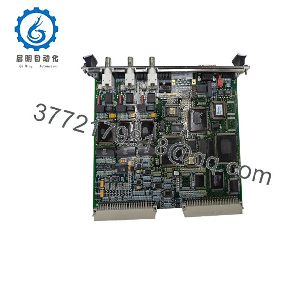
| Physical Network Ports | Three coaxial BNC network connectors (10Base2) |
| Serial Diagnostics | One dedicated RS-232 serial communication port |
| Hardware Controls | Onboard push-button manual reset switch |
| Diagnostic Display | Dedicated Run/Fail LEDs plus 1, 2, 4, 8 Binary Address LEDs |
4. Product Introduction & Supply Chain Strategy
The GE IS215VCMIH2BE is the central communication spine of the Speedtronic Mark VI turbine control platform. Functioning as the dedicated VME Bus Master Controller (VCMI), this 6U high module establishes the critical communication pathway between the main controller boards, individual local I/O modules, and the broader triple-redundant IONet control network. Utilizing an onboard 32-bit Digital Signal Processor and dual-port memory caching, it handles internal bus arbitration, address decoding, and time-coherent data synchronization for local and remote turbine processing racks.
From a supply chain standpoint, maintaining this conformal-coated card as a New Surplus unit is a vital risk-mitigation strategy for power generation facilities. Because the VCMI manages the identification sequence (IDs) for every downstream board in the VME rack, its failure results in a complete rack lockout and immediate plant shutdown. Procuring a New Surplus module avoids the component fatigue, aged solder points, and tracking errors common in refurbished communication cards, lowering your Total Cost of Ownership (TCO) and securing predictable uptime.

- IS215VCMIH2BE
- IS215VCMIH2BE
5. Installation & Configuration Guide
Stage 1: Pre-Installation (Prep & Safety)
- De-energize the main VME control rack power supplies. Isolate associated auxiliary power distribution lines to prevent transient voltages across the backplane.
- Ensure your field tools are static-safe and verify that you are wearing a properly grounded, high-impedance ESD wrist strap.
- Photograph the front panel assembly. Note the exact layout of the coaxial BNC cables connected to the three IONet ports, as swapping these lines disrupts controller synchronization.
Stage 2: Removal
- Unscrew and detach the BNC network cables from the front panel. Carefully unplug any diagnostic serial cables connected to the RS-232 interface.
- Loosen the upper and lower captive fasteners that anchor the VCMI faceplate to the rack frame.
- Pull the card handles outward using steady, horizontal pressure to slide the module clear of the VME chassis tracks, ensuring you do not twist or flex the printed circuit board.
Stage 3: Installation (Clone & Seat)
- Compare the hardware revision, option jumpers, and configuration switches on the replacement IS215VCMIH2BE to ensure an exact match with the original unit.
- Align the card edge with the targeted VME slot guides. Slide the board slowly into the rack until the rear connectors approach the backplane.
- Press the faceplate ejector handles firmly inward to drive the pins home into the backplane socket. Fasten the upper and lower retaining screws securely to the frame.
- Reconnect the three BNC coaxial network cables and the auxiliary serial line to their exact matching ports.
Stage 4: Power-On & Testing
- Re-engage the 24 V DC system power feed to the control rack assembly.
- Monitor the diagnostic faceplate LEDs. The card should quickly complete its boot-up check, showing an active green RUN light, while the network indicators reflect clear TX/RX signaling.
- Connect your Engineering Workstation running the Control System Toolbox to verify the board ID handshake, ensure valid IONet node arbitration, and confirm that all voting loops register zero active communication errors.
6. Firmware/Software Versions & Upgrade Notes
- Onboard EEPROM Sync: The IS215VCMIH2BE reads system configuration data directly from the software profile embedded inside your master application code package. Ensure that the controller configuration inside your Toolbox programming software exactly mirrors this card’s specific H2BE revision.
- Network Baseline Matching: The H2BE version features updated component specifications designed for stable multi-port BNC routing. Mixing older, non-coated VCMI revisions within a shared Triple Modular Redundant (TMR) controller network can trigger systemic timing errors or bus timeouts.
- Firmware Overwrites: Do not download system firmware updates or initiate major configuration rewrites while the turbine is online or spinning. Interrupting the VME bus master during runtime disrupts the local I/O bus communication loop, which will instantly drop your field device connections and cause a full emergency system trip.
7. Frequently Asked Questions (FAQ)
What separates this New Surplus VCMI board from a refurbished equivalent?
Our New Surplus cards are unused, pristine parts sourced directly from project overstock, canceled facility builds, or uninstalled asset reserves. They are stored in climate-controlled warehouses within original protective packaging. Refurbished boards are pulled from decommissioned plants and subjected to multiple thermal cycles, creating latent stresses in the micro-soldering of the DSP chip and the bus arbitration chips. Our New Surplus inventory ensures factory-level longevity and stable operational reliability.
Why is this communication card priced higher than typical used marketplace listings?
The VCMI serves as the single point of management for the entire VME rack’s communication bus. Installing a cheap, unverified used card exposes your plant to significant failure risks, where a single network drop can lead to a costly unscheduled turbine outage. This New Surplus board provides a zero-hour, conformal-coated option that ensures maximum signal stability and long-term protection against harsh industrial environments, offering high return on investment relative to its initial acquisition cost.
Can the IS215VCMIH2BE card be hot-swapped while the turbine is active?
No. The VMEbus architecture does not support live hot-swapping. Pulling or inserting a master controller card while the 24 V DC backplane power is active creates severe voltage arcs across the data pins. This will ruin the 32-bit DSP, damage the dual-port SRAM banks, and likely damage adjacent boards in the rack frame. Always execute a complete, verified power-down sequence before servicing the module.
What is the role of the binary address LEDs labeled 1, 2, 4, and 8 on the faceplate?
These four LEDs provide local, real-world hardware verification of the module’s active rack network identity and status codes. During typical initialization and live run states, these indicators light up in specific binary combinations to indicate the current step of the boot phase, show network error profiles, or confirm the specific active node address within the local Mark VI control arrangement.
How does the conformal coating change the performance of the H2BE version?
The “E” suffix within the H2BE product designation indicates a factory-applied protective conformal coating layer over the entire surface-mount assembly. This thin chemical film protects the sensitive 32-bit processor tracks, resistors, and capacitors from environmental degradation. It safeguards the module against airborne pollutants, conductive dust, high humidity, and localized chemical oxidation inside the cabinet, making it ideal for harsh industrial environments.


