
 WhatsApp: +86 16626708626
 Email:
  Phone: +86 16626708626
Description
3. Key Technical Specifications
| Parameter | Value |
|---|---|
| Manufacturer | General Electric (GE) |
| Model Number | IS215VCMIH2CC |
| Functional Acronym | VCMI |
| Product Type | VME Bus Master Controller |
| System Series | Mark VI Speedtronic |
| Rack Format | 6U VME Board |
| Board Width | 0.787 in (20 mm) |
| Processor | Texas Instruments TMS320C32 32-bit DSP |
| Flash Memory | 4096K x 8 |
| SRAM | 256K x 32 |
| Dual-Port RAM | 32 KB |
| IONet Ports | 3 × 10Base2 Ethernet (BNC) |
| Serial Port | 1 × RS-232C |
| Communication Role | Controller-to-I/O Interface |
| Network Support | Simplex and TMR |
| Frame Rate | 10 ms (Simplex), 40 ms (TMR) |
| Power Monitoring | +5 V, ±12 V, ±15 V, ±28 V |
| Diagnostics | >60 Fault Conditions |
| Operating Temperature | 0 °C to 50 °C Typical |
| PCB Coating | Conformal Coated Revision |
| Mounting | VME Rack Installation |
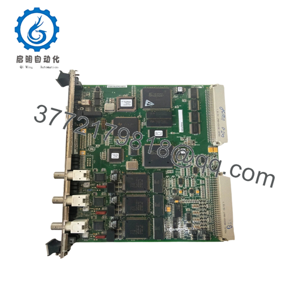
The IS215VCMIH2CC functions as the central communication manager inside a GE Mark VI control system. It serves as the VME bus master, controls board identification, manages terminal board associations, and handles communications between the controller, I/O boards, and the IONet network. The H2 hardware version includes three IONet channels for Triple Modular Redundant (TMR) architectures.
4. Product Introduction
The GE IS215VCMIH2CC is a Mark VI VME Bus Master Controller module used in gas turbine, steam turbine, and power generation control systems. It manages communication between the main controller, local I/O boards, expansion racks, and the system IONet network.
Field engineers typically deploy the IS215VCMIH2CC in TMR systems where communication integrity is critical. The three dedicated IONet channels, onboard DSP processor, and extensive diagnostics make it suitable for large turbine installations with multiple remote I/O racks and strict uptime requirements.

- IS215VCMIH2CC
- IS215VCMIH2CC
5. Installation & Configuration Guide
Stage 1: Pre-Installation Preparation (10 Minutes)
⚠️ Safety First
- Notify operations personnel of the maintenance window.
- Verify the turbine or process is in a safe shutdown state.
- Lock out and tag out all cabinet power sources.
- Wait at least 5 minutes for DC bus discharge.
- Verify voltage absence using a Fluke 115 or equivalent meter.
Tools Required
- Grounded ESD wrist strap
- PH1 screwdriver
- Fluke 115 multimeter
- Wire labels
- Smartphone camera
- ESD mat
- Flashlight
Data Backup
- Backup ToolboxST project files.
- Export current controller configuration.
- Record:
- Rack location
- Node assignments
- IP settings
- IONet configuration
- Photograph:
- Front faceplate
- BNC network connections
- Serial cable connections
- Rack slot location
❗ Before touching the board, document the firmware version. I’ve seen replacement VCMI boards boot normally but refuse to synchronize because one rack was running a different firmware family.
Stage 2: Removing the Old Module (5 Minutes)
- Open cabinet access panels.
- Label all communication cables.
- Disconnect:
- IONet BNC cables
- Serial connection
- Associated rack wiring
- Release front retaining screws.
- Pull the module straight outward.
⚠️ Do not twist the board while removing it. VME backplane connectors can be damaged surprisingly easily.
- Inspect:
- VME connector pins
- Dust accumulation
- Corrosion
- Bent contacts
⚠️ Do not discard the old board until the replacement passes full operational testing.
Stage 3: Installing the New Module (10 Minutes)
1. ESD Preparation
- Wear grounded wrist strap.
- Place module on ESD-safe surface.
- Verify exact part number:
IS215VCMIH2CC
Do not assume H2C, H2CB, H2CA, and H2CC revisions are interchangeable without checking system requirements.
2. Configuration Clone (Critical)
Compare all recorded settings.
Verify:
- Network assignments
- Rack addressing
- Redundancy configuration
- Firmware revision compatibility
❗ This is where many commissioning delays start. Somebody installs the board, skips verification, then spends six hours chasing a communication fault that was documented before removal.
3. Install the Module
- Align with VME guide rails.
- Slide board evenly into rack.
- Fully seat connector.
- Tighten retaining hardware.
You should feel firm connector engagement before tightening screws.
4. Reconnect Network Connections
- Reconnect all IONet BNC cables.
- Verify channel assignments.
- Reconnect serial diagnostics port if used.
- Check cable strain relief.
Self-Checklist
- Correct model verified
- Firmware documented
- Network cables reconnected
- Rack fully seated
- Retaining screws secured
- ESD procedures followed
Stage 4: Power-On & Testing (15 Minutes)
Pre-Power Check
- Verify cabinet grounding.
- Measure 24 V supply rails.
- Check for short circuits.
Power-Up Procedure
- Energize the control rack only.
- Observe front panel LEDs.
Expected status:
- RUN = Green
- FAIL = Off
- STATUS = Normal operation indication
- Connect ToolboxST.
- Verify:
- Module recognition
- IONet communication
- Rack inventory
- Firmware revision
- Diagnostic status
- Validate board identification mapping.
- Verify all remote racks communicate correctly.
- Perform I/O scan verification.
⚠️ Troubleshooting Note
- FAIL LED Red: Check firmware mismatch or topology mismatch.
- IONet Offline: Verify coax termination and BNC cable assignments.
- Board ID Faults: Check terminal board associations and topology files.
Common Field Pitfalls Engineers Encounter
❗ Firmware Revision Mismatch
The VCMI controls rack identification and communication management. Firmware mismatches can affect the entire rack.
I worked a gas turbine outage where one replacement board introduced a newer firmware build. The controller came online, but the remote I/O racks continuously generated topology faults.
Avoidance: Record existing firmware and request matching revisions when sourcing replacements.
❗ IONet Cable Misplacement
The H2 version uses three IONet channels in TMR systems.
Swapping R, S, and T channels creates communication alarms that can look like controller failures.
Avoidance: Label every cable before removal.
❗ Board Identification Mismatch
The VCMI validates board IDs and terminal board assignments.
A mismatch can prevent startup.
Avoidance: Verify hardware inventory against the topology file before energizing.
❗ Power Supply Margin Problems
Adding remote I/O racks increases loading.
I’ve seen cabinets run fine for years until a replacement board pushed a marginal supply into undervoltage alarms.
Avoidance: Maintain at least 20% spare power capacity.
❗ Electrostatic Discharge (ESD)
These DSP-based boards are not forgiving.
A technician once unpacked a VCMI module directly on a painted steel cabinet without grounding himself. The board failed memory diagnostics immediately after power-up.
Avoidance: Wrist strap, ESD mat, anti-static handling. Every installation.
Keep these checks in mind and you’ll save yourself 90% of typical rework time.
6. Frequently Asked Questions (FAQ)
Q1. Can I hot-swap the IS215VCMIH2CC?
No.
Despite some aftermarket listings claiming hot-swap capability, the VCMI is the VME bus master for the rack. Removing it under power risks communication loss, VME bus faults, and potential backplane damage.
Power down the rack first.
Q2. Is the IS215VCMIH2CC obsolete?
Yes.
The Mark VI platform remains widely installed, but IS215VCMIH2CC is no longer current-production GE hardware.
Most available inventory consists of:
- New Surplus
- OEM Spare Stock
- Tested Refurbished Units
Availability can become tight during major turbine outage seasons.
Q3. What is the difference between H2C, H2CB, and H2CC revisions?
The core function remains the same, but revision levels may include:
- Firmware differences
- Memory capacity changes
- Coating variations
- Hardware updates
Always verify compatibility against your existing Mark VI system documentation before installation.
Q4. Will replacing the VCMI erase my turbine control logic?
Normally no.
The VCMI manages communications and rack control. Application logic remains stored in the controller system.
That said, never start a maintenance job without a verified backup.
Q5. Why does the IS215VCMIH2CC have three IONet ports?
The H2 hardware revision supports Triple Modular Redundant (TMR) systems.
The three independent IONet channels provide separate communication paths for R, S, and T controllers, allowing voting logic and fault tolerance.
Q6. What testing should be performed before shipment?
A proper incoming and outgoing QC process should include:
- OEM label verification
- Serial number traceability review
- Visual inspection under magnification
- Power-on testing in a genuine Mark VI rack
- IONet communication testing
- Board ID verification
- 24-hour thermal run test
- 500 V insulation resistance test (>10 MΩ)
- Firmware documentation
- QC sign-off and anti-static packaging
Test reports, startup photos, and operation videos should be available upon request.
Q7. Why are New Surplus units usually preferred over refurbished boards?
For critical turbine control applications, New Surplus units reduce uncertainty around prior operating history.
That said, a properly tested refurbished module can perform reliably if the supplier provides:
- Functional test records
- Firmware verification
- Communication test results
- Electrical inspection reports
- Traceability documentation
The paperwork often tells you more about reliability than the cosmetic condition of the board itself.


