
 WhatsApp: +86 16626708626
 Email:
  Phone: +86 16626708626
Description
3. Key Technical Specifications
| Parameter | Value |
|---|---|
| Manufacturer | General Electric (GE) |
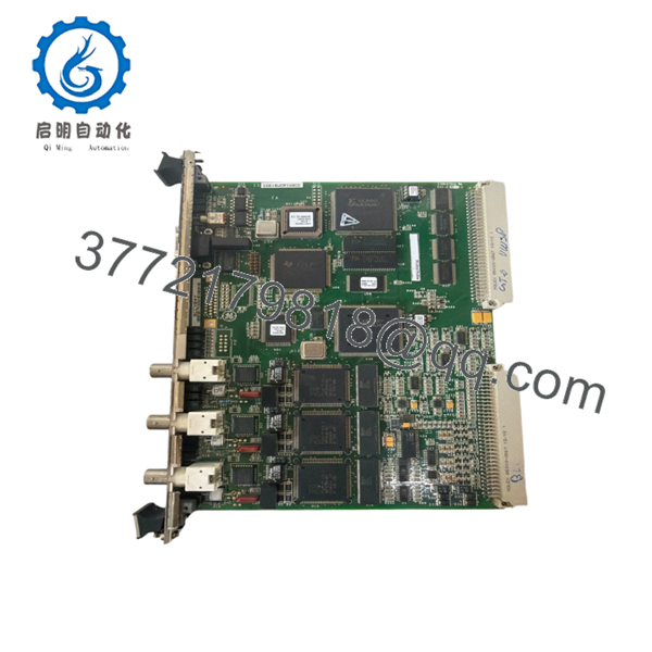
| Model Number | IS215VCMIH2CC |
| Product Type | VME Bus Master Controller Module |
| Functional Acronym | VCMI |
| Series | Mark VI Speedtronic |
| Rack Architecture | 6U VME |
| Processor | Texas Instruments TMS320C32 32-bit DSP |
| Communication Network | GE IONet |
| IONet Ports | 3 × 10Base2 Ethernet (BNC) |
| Serial Interface | 1 × RS-232C |
| Bus Interface | VME Backplane |
| Redundancy Support | TMR (Triple Modular Redundancy) |
| Flash Memory | 4096K × 8 |
| SRAM | 256k × 32 |
| Dual-Port RAM | 32 KB |
| Diagnostic Capability | Power bus and topology monitoring |
| Supported Frame Rates | 10 ms, 20 ms, 40 ms, 80 ms |
| Power Monitoring | ±12 V, ±15 V, ±28 V, +5 V |
| Operating Temperature | Typically 0 °C to 50 °C |
| Width | 0.787 in (20 mm) |
| Configuration Tool | GE ToolboxST |
| Application | Gas and Steam Turbine Control Systems |
| Condition Options | New Original, New Surplus, Refurbished (tested) |
The IS215VCMIH2CC functions as the communication master inside GE Mark VI control systems. It coordinates I/O communication across the VME backplane and interfaces the control rack with the GE IONet deterministic network.
4. Product Introduction
The GE IS215VCMIH2CC is a VME Bus Master Controller module used in GE Mark VI turbine control systems. It manages communication between the controller, I/O modules, remote racks, and protection systems through the GE IONet architecture.
In field deployments of Mark VI TMR systems, the IS215VCMIH2CC is one of the critical rack communication boards. Engineers typically use this revision in systems requiring triple IONet channels, deterministic data exchange, and compatibility with existing VME-based turbine controls.

- IS215VCMIH2CC
- IS215VCMIH2CC
5. Installation & Configuration Guide
Stage 1: Pre-Installation Preparation (Estimated Time: 10 Minutes)
⚠️ Safety First
- Notify operations before taking the control rack offline.
- Place the turbine or driven process into a verified safe shutdown state.
- Apply lock out/tag out procedures to all related power feeds.
- Wait at least 5 minutes for cabinet capacitors to discharge fully.
- Verify absence of voltage using a Fluke 115 or equivalent multimeter.
Tools Required
- ESD wrist strap
- PH1 screwdriver
- Multimeter
- Wire labels
- Smartphone for documentation photos
- Flashlight
Data Backup
- Export current Mark VI configuration files from ToolboxST.
- Record all IONet addressing and rack assignments.
- Photograph every DIP switch and jumper position clearly.
- Capture terminal wiring and coax routing before disconnecting cables.
❗ This sounds basic, but I still see experienced maintenance crews skip it during outage pressure. Ten minutes of photos can save half a shift of troubleshooting later.
Stage 2: Removing the Old Module (Estimated Time: 5 Minutes)
- Remove the front cabinet panel or protective bezel.
- Label all communication cables before disconnecting them.
- Disconnect BNC IONet cables carefully. Do not twist aggressively.
- Release VME rack retention tabs.
- Pull the module straight outward.
⚠️ Important
Never rock the board side-to-side excessively. Bent VME backplane pins turn a quick board swap into a rack repair job.
- Inspect the rack:
- Bent connector pins
- Dust contamination
- Corrosion
- Loose grounding hardware
⚠️ Keep the old module
Do not discard or return the original module until the replacement runs cleanly under load.
Stage 3: Installing the New Module (Estimated Time: 10 Minutes)
- Attach your ESD strap before touching the replacement board.
- Verify:
- Exact model number
- Hardware suffix
- Firmware compatibility
- TMR versus Simplex configuration
❗ Configuration Clone (Critical)
Replicate all DIP switches and jumper settings exactly from the original board.
This is the most common replacement failure I see in legacy GE racks. A single wrong node address or termination setting can stop the entire IONet from initializing correctly.
- Insert the IS215VCMIH2CC evenly into the VME rack guides.
- Push firmly until fully seated.
- Tighten front retention screws evenly.
- Reconnect all BNC and serial connections carefully.
Self-Checklist
- DIP switches cloned correctly
- BNC connections secured
- Rack tabs locked
- Grounding verified
- No pin damage visible
Stage 4: Power-On & Testing (Estimated Time: 15 Minutes)
Pre-Power Check
- Verify no shorts exist on the 24 VDC rail.
- Confirm cabinet grounding continuity.
- Inspect coaxial IONet termination integrity.
Power-On Procedure
- Energize the rack only.
- Observe LED startup behavior:
- RUN LED green = normal
- FAIL or ERR red = fault condition
- Connect ToolboxST engineering software.
- Verify:
- Firmware revision
- Rack communication
- IONet visibility
- Board identification
- Restore configuration if required.
- Perform dry-run I/O validation before enabling field outputs.
⚠️ Firmware Revision Mismatch
This catches people constantly on older Mark VI systems.
I’ve seen techs install a later VCMI revision and spend two days chasing communication alarms because the firmware differed slightly from the rest of the rack. The controller stayed online, but IONet timing drifted enough to trigger intermittent faults.
Before removal:
- Record firmware versions
- Match firmware ranges whenever possible
- Verify ToolboxST compatibility
⚠️ DIP Switch and Jumper Errors
Take a picture before you pull the board. Seriously.
Factory default settings rarely match the live plant configuration. Node addressing and bus termination settings matter on these systems.
⚠️ Power Supply Loading
Do not assume the original power supply has spare capacity.
The VCMI itself is moderate in consumption, but fully loaded Mark VI racks with multiple communication and I/O modules can overload aging 24 VDC supplies quickly. Leave at least 20% headroom.
⚠️ ESD Handling
Always use grounding protection.
I once watched a contractor swap a GE communication board during dry winter conditions without an ESD strap. The board booted once, then failed permanently after the second power cycle. Expensive mistake.
Keep these checks in mind and you’ll save yourself 90% of typical rework time.
6. Frequently Asked Questions (FAQ)
Q1: Can the IS215VCMIH2CC be hot-swapped?
No.
This module is not intended for live insertion. Pulling a VME communication board under power risks damaging the backplane or crashing rack communications. Shut the rack down completely before replacement.
Q2: Is the IS215VCMIH2CC obsolete?
Yes. The Mark VI platform is considered a legacy GE turbine control system.
However, many gas and steam turbine installations worldwide still rely on these racks daily. New surplus and tested refurbished inventory remains available through the industrial surplus market.
Q3: What is the difference between H1 and H2 VCMI versions?
The H2 revision includes three IONet ports intended for TMR architectures. Earlier H1 variants generally support fewer communication channels.
Always verify:
- Rack topology
- IONet structure
- Existing firmware revision
- System redundancy requirements
before ordering a replacement.
Q4: Will replacing this board erase my turbine logic?
Normally, no.
The IS215VCMIH2CC primarily manages communications and rack coordination. Application logic usually resides elsewhere in the control architecture. That said, always back up the system before shutdown. Never trust undocumented legacy systems.
Q5: Why do some replacement boards fail immediately after installation?
The most common causes are:
- Incorrect DIP switch settings
- Firmware mismatch
- Bent VME backplane pins
- Faulty IONet termination
- ESD damage during handling
Honestly, DIP switch errors alone probably account for half the startup failures I see on older turbine systems.
Q6: Are your modules tested before shipment?
A proper QC process should include:
- OEM traceability inspection
- Serial number verification
- Visual inspection for corrosion or rework
- Power-on testing on a genuine or compatible GE Mark VI rack
- IONet communication testing
- Insulation resistance testing using a 500 V Megger
- Burn-in testing under load
- ESD-safe packaging and QC sign-off
Verified fully functional under load testing. Test reports and startup videos should be available upon request.
Q7: Why is secondary-market pricing lower than OEM pricing?
Most available inventory comes from:
- Plant surplus stock
- Turbine retrofit projects
- Decommissioned facilities
- Unused project spares
You’re usually buying from the industrial surplus channel rather than fresh OEM production lines. That is normal for legacy turbine control hardware.


