
 WhatsApp: +86 16626708626
 Email:
  Phone: +86 16626708626
Description
Key Technical Specifications
| Parameter | IS215WEPAH2AB Specification | IS210BPPBH2CAA Specification |
| Manufacturer | GE (General Electric) | GE (General Electric) |
| Series Compatibility | Mark VIe Control Systems | Mark VI Speedtronic Systems |
| Primary Subsystem | Wind Pitch Axis Axis Control | Backup Protection Processor (BPPB) |
| Prime Mover Application | Wind Energy Generation Assets | Gas and Steam Power Turbines |
| Redundancy Support | Dual-channel control paths | Triple Modular Redundant (TMR) ready |
| Hardware Components | High-speed DSP and communication chips | 8 plug connectors, 6 metal oxide varistors |
| Humidity Range | 5% to 95% non-condensing | 5% to 95% non-condensing |
| Operating Temperature | −30 to +65 °C (−22 to 149 °F) | 0 to +60 °C (32 to 140 °F) |
| Mounting Style | Integrated chassis / enclosure base | Stand-off metal chassis mounting |
Product Introduction & Supply Chain Strategy
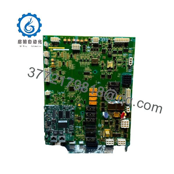
The combination of the GE IS215WEPAH2AB Wind Pitch Axis Control Module and the IS210BPPBH2CAA Backup Protection Processor Board forms a critical protective foundation within heavy industrial power generation sectors. The IS215WEPAH2AB delivers precise positioning and real-time monitoring of wind turbine rotor blades under highly dynamic wind loads. Concurrently, the IS210BPPBH2CAA operates as an independent safety barrier in gas and steam environments, running hardware-based emergency trip logic and overspeed protection routines outside the primary application processors.
Maintaining these components as New Surplus units is vital to limiting the Total Cost of Ownership (TCO) across complex power generation networks. Because factory-backed supply lines for these legacy lines are severely constrained, relying on cheap refurbished boards introduces immediate risk from invisible thermal fatigue and degraded metal oxide varistors. Allocating strategic investment to secure factory-sealed hardware eliminates the secondary costs of extended emergency outages and safeguards your plant’s overall availability targets.

- IS215WEPAH2AB
- IS215WEPAH2AB
Installation & Configuration Guide
Stage 1: Pre-Installation (Prep & Safety)
- De-energize the entire control enclosure pane and confirm all upstream breakers are verified through clear lock-out/tag-out steps.
- Put on a calibrated, grounded ESD wrist strap before unlocking the static-sensitive module storage boxes.
- Take detailed digital photographs of all input connections, terminal blocks, plug positions, and existing mounting frameworks.
Stage 2: Removal
- Unplug the structural terminal block wiring plugs from the front face of the IS210BPPBH2CAA card straight outward.
- Loosen all stand-off frame mounting screws systematically to relieve mechanical tension on the backplane joints.
- Slide the IS215WEPAH2AB card assembly clear of its chassis guidelines, lifting exclusively by the structural edges to avoid trace contamination.
Stage 3: Installation (Clone & Seat)
- Unbox the New Surplus board inside an ESD-protected zone and verify that no alignment pins were warped during freight transport.
- Match all internal jumper matrices and firmware DIP settings on the replacement PCB to mirror the removed board identically.
- Line up the card with the mounting rails, pushing the unit into position until all plug interfaces line up smoothly without binding.
- Fasten all framing hardware securely to prevent vibration displacement during turbine operation.
Stage 4: Power-On & Testing
- Use an isolated digital multimeter to measure input lines, confirming that steady 24 V DC power is delivered without ground faults.
- Power up the master control framework and observe the initialization diagnostic LEDs to verify that the board clears all boot-up checks.
- Launch your Control System Toolbox utility to monitor physical I/O handshake links and verify active loop communication status.
Firmware/Software Versions & Upgrade Notes
The IS215WEPAH2AB module and IS210BPPBH2CAA board rely on specific core software alignments managed via GE ToolboxST configuration platforms. Hardware revisions—such as the transition from revision AA to AB or CAA variants—often dictate underlying chip speeds and functional communication layouts.
Before initiating a hardware swap, read out the existing runtime application software and application code from the active rack. Forcing an unverified board revision change into an older system configuration can trigger severe protocol timeouts or lock up the primary turbine emergency trip circuits. Avoid flashing or altering active firmware blocks mid-stream during a direct replacement action unless directed by a specific engineering bulletin.
Frequently Asked Questions (FAQ)
Q: Why does the pricing for these components exceed common refurbished options found online?
A: Our components are verified New Surplus units that have never seen actual operation in a field environment. Refurbished parts are frequently salvaged from decommissioned facilities and run a high risk of failure due to worn components like aged varistors or failing capacitors. The higher investment for genuine surplus stock guarantees a full 10–15 year operating life, eliminating the risk of sudden downtime that can cost thousands of dollars per hour.
Q: Are these boards genuinely new, and how do you ensure their long-term storage safety?
A: Yes, these are unused, authentic OEM parts. We store all industrial circuit boards inside temperature-regulated environments inside specialized static-sensitive boxes. They are handled using strict ESD safety regulations and are opened only to run final inbound visual quality control checks.
Q: Can the IS210BPPBH2CAA board be replaced while the turbine control module is running?
A: No. You must never hot-swap the backup protection processing card while the rack has power active. Because it is directly wired to emergency trip logic and critical power distribution circuits, pulling the card live can trigger accidental emergency plant trips or generate destructive voltage spikes across the system backplane.
Q: Do these specific model numbers support CANBus operations within wind turbine frameworks?
A: The IS215WEPAH2AB is explicitly designed as a non-CANBus wind pitch axis control module variant. If your turbine configuration uses a CANBus architecture for pitch control tracking, you must check your documentation to confirm whether you need the legacy H1A/H1AB modules instead.
Q: What type of hardware warranty protection do you provide for these surplus boards?
A: We provide a comprehensive 1-year operational replacement warranty on all New Surplus modules. This coverage safeguards your facility against unexpected material flaws or component failure under normal operating loads from day one.


