
 WhatsApp: +86 16626708626
 Email:
  Phone: +86 16626708626
Description
3. Key Technical Specifications
| Parameter | Value |
|---|---|
| Manufacturer | General Electric (GE) |
| Model Number | IS220PTCCH1B |
| Functional Acronym | PTCC |
| Product Type | Thermocouple Input Module |
| System Series | Mark VIe / Mark VIeS |
| Input Channels | 12 Thermocouple Inputs |
| Cold Junction Compensation | 1 Integrated Cold Junction |
| Supported Thermocouples | E, J, K, S, T |
| Input Signal Range | -8 mV to +45 mV |
| Power Supply | 28 VDC Nominal |
| Current Consumption | 0.16 A Maximum |
| Ethernet Ports | Dual 100 Mbps Full Duplex RJ45 |
| Communication Interface | IONet Ethernet |
| Terminal Board Compatibility | TBTCH1B, TBTCH1C |
| Cable Distance | Up to 984 ft (300 m) |
| Maximum Cable Resistance | 450 Ω |
| System Architecture | Simplex, Duplex, TMR |
| Diagnostics | RAM, Flash, Ethernet, Processor Self-Test |
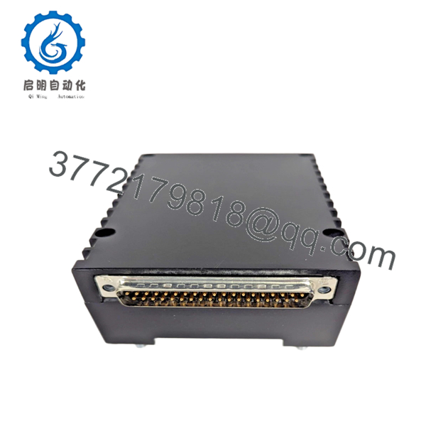
| Output Connector | DC-37 Connector |
| Operating Temperature | -30 °C to +65 °C |
| PCB Protection | Conformal Coated |
| Weight | Approximately 1 lb (0.45 kg) |
The GE IS220PTCCH1B is a distributed I/O thermocouple pack designed for combustion and turbine temperature monitoring applications within Mark VIe and Mark VIeS control systems. The pack digitizes thermocouple signals locally and transfers data across the IONet network to the controller. It supports both grounded and ungrounded thermocouple installations.
4. Product Introduction
The GE IS220PTCCH1B is a PTCC thermocouple input pack used in Mark VIe and Mark VIeS turbine control systems. It provides temperature acquisition for combustion monitoring, exhaust temperature supervision, and turbine protection functions using standard industrial thermocouples.
Engineers commonly deploy the IS220PTCCH1B in gas turbine applications requiring accurate temperature feedback and high system availability. The module supports simplex, duplex, and Triple Modular Redundant (TMR) architectures while providing onboard diagnostics, integrated cold-junction compensation, and dual Ethernet communication paths.

- IS220PTCCH1B
5. Installation & Configuration Guide
Stage 1: Pre-Installation Preparation (10 Minutes)
⚠️ Safety First
- Notify plant operations and obtain maintenance approval.
- Place the turbine or controlled process in a verified safe condition.
- Lock out and tag out all control cabinet power sources.
- Wait at least 5 minutes for internal power rails to discharge.
- Verify absence of voltage using a calibrated Fluke 115 multimeter.
Tools Required
- Grounded ESD wrist strap
- ESD work mat
- PH1 screwdriver
- Fluke 115 multimeter
- Wire markers
- Smartphone camera
- Flashlight
Data Backup
- Backup current ToolboxST project files.
- Export controller configuration data.
- Record:
- IONet IP addresses
- Rack assignments
- Redundancy configuration
- Photograph:
- Existing PTCC installation
- Ethernet connections
- Terminal board wiring
- Connector orientation
❗ Before removing anything, record the firmware revision. I’ve seen a replacement PTCC boot normally but refuse to synchronize with older Mark VIe firmware because the I/O pack revision was several generations newer.
Stage 2: Removing the Old Module (5 Minutes)
- Open cabinet access panels.
- Label all thermocouple wiring.
- Disconnect Ethernet cables.
- Disconnect power connector.
- Release mechanical retaining hardware.
- Carefully unplug the PTCC pack from the terminal board.
⚠️ Do not pull sideways against the DC-37 connector. Those connectors can bend surprisingly easily.
- Inspect:
- Terminal board connector alignment
- Ethernet ports
- Grounding hardware
- Corrosion or contamination
⚠️ Keep the original module available until the replacement completes commissioning successfully.
Stage 3: Installing the New Module (10 Minutes)
1. ESD Preparation
- Wear grounded wrist strap.
- Place module on ESD-safe surface.
- Verify exact model:
IS220PTCCH1B
Do not assume PTCCH1A and PTCCH1B revisions are automatically interchangeable.
2. Configuration Clone (Critical)
Verify:
- Ethernet network assignments
- TMR configuration
- Terminal board type
- Firmware compatibility
❗ This is the most common rookie mistake, but experienced engineers still get caught by it during outage pressure. Take pictures before removal and duplicate the setup exactly.
3. Install the Module
- Align module with terminal board connector.
- Insert evenly.
- Secure mounting studs.
- Verify no side-load exists on the DC-37 connector.
4. Reconnect Wiring
- Reconnect Ethernet ports.
- Reconnect power connector.
- Verify strain relief.
- Confirm thermocouple wiring identification.
Self-Checklist
- Correct model verified
- Ethernet connections restored
- Connector fully seated
- Hardware secured
- Firmware documented
- ESD procedures followed
Stage 4: Power-On & Testing (15 Minutes)
Pre-Power Check
- Verify cabinet grounding.
- Check 28 VDC supply.
- Measure resistance to detect shorts.
Power-Up Procedure
- Energize control cabinet power.
- Observe diagnostic LEDs.
Expected behavior:
- RUN LED = Green
- FAULT LED = Off
- Network activity LEDs = Flashing
- Connect ToolboxST.
- Verify:
- PTCC recognition
- Firmware version
- Ethernet communication
- Channel status
- Validate all thermocouple inputs.
- Compare displayed temperatures against known process conditions.
- Verify alarm and trip thresholds.
⚠️ Troubleshooting Note
- Solid Fault LED: Check firmware compatibility.
- No Ethernet Communication: Verify IONet addressing and switch ports.
- Temperature Drift: Check grounding and cold-junction integrity.
- Input Saturation: Inspect thermocouple polarity and cable shielding.
Common Field Pitfalls Engineers Encounter
❗ Firmware Revision Mismatch
Mark VIe I/O packs are sensitive to firmware family compatibility.
During a combustion system outage, I watched a replacement PTCC spend an entire shift generating communication faults because the replacement firmware revision was newer than the controller baseline.
Avoidance: Record firmware before removal and request matching revisions during procurement.
❗ Thermocouple Polarity Reversal
This happens constantly.
A reversed thermocouple often produces believable but incorrect readings.
The control system may never declare a hard fault.
Avoidance: Verify polarity wire-by-wire during reconnection.
❗ Grounded vs Ungrounded Sensor Confusion
The PTCC supports both grounded and ungrounded thermocouples.
Mixing installation assumptions can create noise, drift, and unstable readings.
Avoidance: Verify field instrument specifications before commissioning.
❗ Power Supply Loading
Many technicians focus only on I/O replacement and forget cabinet power calculations.
The PTCC itself draws modest current, but multiple I/O packs can overload an aging supply.
Avoidance: Maintain at least 20% spare capacity on the 28 VDC rail.
❗ Electrostatic Discharge (ESD)
I once watched a contractor unpack a new I/O pack directly on a painted steel cabinet during winter. The module passed power-up but failed Ethernet diagnostics within minutes.
That board never returned to service.
Avoidance: Ground strap, ESD mat, anti-static handling every time.
Keep these checks in mind and you’ll save yourself 90% of typical rework time.
6. Frequently Asked Questions (FAQ)
Q1. Can I hot-swap the IS220PTCCH1B?
No.
GE does not recommend removing or installing the PTCC pack under power. Disconnecting the module live can interrupt IONet communication and potentially damage the connector interface.
Shut down cabinet power first.
Q2. Is the IS220PTCCH1B obsolete?
Yes.
The Mark VIe platform remains heavily deployed worldwide, but many IS220PTCCH1B units now come from:
- New Surplus inventory
- Strategic spare stock
- Tested refurbished inventory
Availability can tighten during major gas turbine outage seasons.
Q3. How many thermocouples can one IS220PTCCH1B handle?
One pack supports 12 thermocouple inputs.
Using compatible terminal board configurations, multiple packs can support expanded input counts or TMR architectures.
Q4. What thermocouple types are supported?
The module supports:
- Type E
- Type J
- Type K
- Type S
- Type T
It also accepts millivolt inputs from -8 mV to +45 mV.
Q5. Will I lose configuration data if I replace the PTCC?
Normally no.
The PTCC functions as a distributed I/O pack. System configuration and application logic remain stored within the controller environment.
Still, always perform a complete backup before maintenance.
Q6. What testing should be completed before shipment?
A proper QC process should include:
- OEM label verification
- Serial number traceability review
- Visual inspection for corrosion or repair marks
- Power-up testing on a genuine Mark VIe rack
- Ethernet communication verification
- Thermocouple simulation testing
- 24-hour thermal run test
- 500 V insulation resistance test (>10 MΩ)
- Firmware documentation
- Final QC sign-off and ESD packaging
Test reports, startup videos, and photos should be available upon request.
Q7. Why do some New Surplus units cost less than OEM pricing?
Most New Surplus inventory comes from:
- Cancelled turbine projects
- Utility spare-parts programs
- Plant modernization projects
- Excess distributor inventory
The hardware may never have been energized, but storage history still matters.
That’s why incoming inspection, firmware verification, and functional testing are more important than appearance alone.


