
 WhatsApp: +86 16626708626
 Email:
  Phone: +86 16626708626
Description
3. Key Technical Specifications
| Parameter | Value / Description |
|---|---|
| Manufacturer | GE Multilin |
| Order Code | 369-HI-R-M-0-0 |
| Product Type | Motor Management Relay |
| Control Power (HI) | 50–300 VDC / 40–265 VAC (or 60–265 VAC per revision) |
| RTD Inputs (R) | 12 built-in 3-wire RTD inputs |
| Metering Option (M) | Included (voltage, power, energy, demand, etc.) |
| Phase Current Inputs | 1 A or 5 A secondary (configurable) |
| Ground Current | Supported |
| Key Protection Functions | Thermal overload (49), short circuit, ground fault, unbalance, stall, undercurrent, etc. |
| Communications | RS232 / RS485 (Modbus) typical; confirm exact ports |
| Display | LCD with keypad |
| Mounting | Panel / non-drawout |
| Operating Temperature | Typically –40°C to +60°C |
| Software | EnerVista 369 |
Exact current transformer ratios, voltage inputs, output relay configuration, and any later protocol options must be verified on the unit nameplate and in the relay settings.
4. Product Introduction
The GE Multilin 369-HI-R-M-0-0 is a digital motor management relay from the 369 series. It provides comprehensive protection, control, and monitoring for three-phase AC motors and their associated mechanical systems.
This specific order code includes high-range control power (HI), twelve built-in RTD temperature inputs (R), and the metering package (M). The relay can learn motor characteristics, offers FlexCurve custom overload protection, event recording, waveform capture, and detailed metering of current, voltage, power, and energy. It is widely used on medium-voltage and larger low-voltage motors in industrial, mining, and process applications.
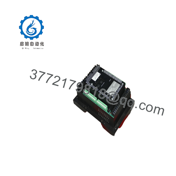
369-HI-R-M-0-0
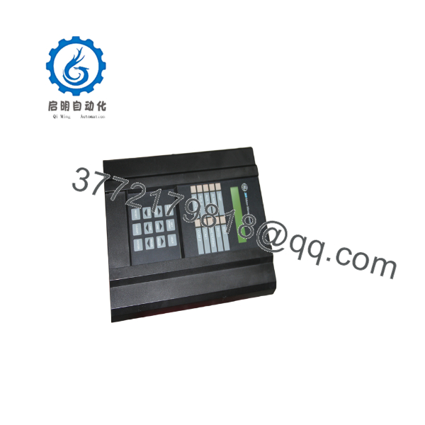
369-HI-R-M-0-0
5. Installation & Configuration Guide
Stage 1: Pre-Installation Preparation (≈15–20 min) ⚠️ Safety First: Isolate all power sources including control power, CT circuits, and VT circuits. Short CT secondaries before disconnecting. Apply lock-out/tag-out. Tools Required: Appropriate screwdrivers, CT shorting blocks if needed, laptop with EnerVista 369 software, serial or network cable. Documentation: Photograph existing wiring, nameplate, and settings. Back up the current relay configuration file.
Stage 2: Removing the Old Relay (≈15–30 min)
- Verify zero energy on all circuits.
- Disconnect control power, CT, VT, RTD, digital I/O, and communication cables.
- Remove mounting hardware and withdraw the relay.
- Inspect terminal blocks and wiring for damage. ⚠️ Keep CT secondaries shorted until the new relay is fully connected.
Stage 3: Installing the New Relay (≈20–40 min)
- Confirm the incoming unit is 369-HI-R-M-0-0 and matches required options.
- Mount the relay in the panel cut-out.
- Land all wiring according to the original drawings and the relay terminal map (control power, CTs, VTs, RTDs, outputs, communications).
- Remove CT shorting links only after connections are verified. Self-Checklist: [ ] Correct order code [ ] CT polarity correct [ ] RTD wiring correct [ ] Control power polarity/voltage correct.
Stage 4: Power-On & Testing (≈30–60 min) Pre-Power Check: Visual inspection and insulation checks as required. Power-On Steps:
- Apply control power and verify display and self-test.
- Load or enter the configuration (setpoints, CT/VT ratios, RTD types, protection elements).
- Perform secondary injection testing of critical protection functions if required by site procedures.
- Verify metering values under load or with test equipment.
- Check communications and event recording.
- Return the motor to service under controlled conditions and monitor initial starts. ⚠️ Troubleshooting Note: Incorrect CT ratio or polarity, wrong RTD type selection, and control power range mismatch are common commissioning issues.
6. Frequently Asked Questions (FAQ)
Q: What does each part of the order code mean?
- HI = High-range control power
- R = 12 built-in RTD inputs
- M = Metering package
- 0-0 = No additional options in those positions (e.g., no fiber or specific fieldbus in the base code)
Q: Is this relay still in current production? The classic 369 series is a mature/legacy product. Newer GE Multilin motor protection relays (e.g., 469, 869, or P24x/P34x families) are the current platforms. The 369 remains widely supported on the secondary market.
Q: Can I upgrade options later? Some options can be enabled in the field with a passcode from GE Multilin. Confirm capability for your specific firmware revision.
Q: What software is used for configuration? EnerVista 369 (or the appropriate EnerVista suite version that supports the 369). Always back up settings before making changes.
Q: Does it support both 1 A and 5 A CTs? Yes, phase current inputs are configurable for 1 A or 5 A secondary.
Q: Why is the price lower than a new motor protection relay? This is a legacy model sold as new surplus or tested secondary-market equipment. Pricing reflects condition, residual demand, and the fact that it is no longer the current-generation catalog product.
Q: What should I verify before installation? Confirm the full order code, control power range, presence of the RTD and metering options, CT/VT ratios, and that the configuration file or setpoints match the motor application. Perform a full functional check after installation.



