
 WhatsApp: +86 16626708626
 Email:
  Phone: +86 16626708626
Description
3. Key Technical Specifications
| Parameter | Value |
|---|---|
| Control Power | HI: 50–300 VDC / 40–265 VAC |
| RTD Inputs | 12 built-in RTD inputs |
| Metering Package | Included (M) |
| Fiber Optic Port | Included (F) |
| Enhanced Features | Enhanced diagnostics / interface (E) |
| Phase Current Inputs | 1 A or 5 A secondary |
| Communications | RS-232 front; RS-485 rear (Modbus RTU standard); optional protocols |
| Display | Enhanced front-panel interface |
| Protection Functions | Overload (standard + FlexCurve), short circuit, ground fault, mechanical jam, undercurrent, etc. |
| Event Recording | Last 512 events (typical) |
| Operating Temperature | –40 °C to +60 °C |
| Enclosure / Pollution Degree | Pollution Degree 2; Overvoltage Category II |
| Software | EnerVista 369 Setup |
4. Product Introduction
The GE Multilin 369-HI-R-M-F-E-0-0 is a digital motor management relay from the 369 series. It provides comprehensive protection, control, and monitoring for three-phase motors and their associated mechanical systems.
The order code indicates high-range control power (HI), 12 built-in RTD inputs (R), the metering package (M), a fiber-optic port (F), and enhanced diagnostics/interface features (E). The relay can learn individual motor parameters (inrush, cooling rates, acceleration time) and adapt its protection curves, including the FlexCurve custom overload characteristic. It supports standard Modbus RTU communications and offers extensive event recording and diagnostics. This model is discontinued.
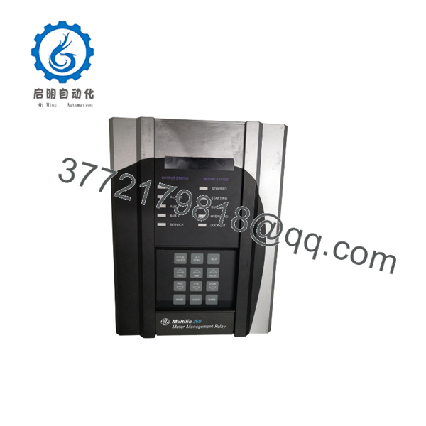
369-HI-R-M-F-E-0-0
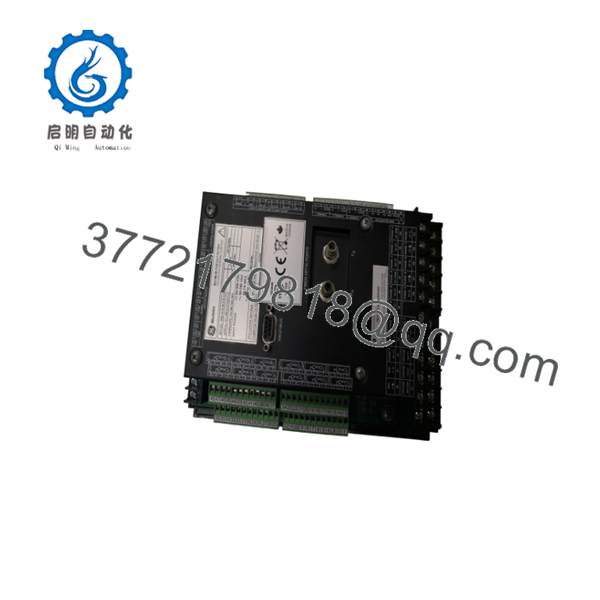
369-HI-R-M-F-E-0-0
5. Installation & Configuration Guide
Stage 1: Pre-Installation Preparation (15–20 min) ⚠️ Safety First: De-energize the motor circuit and control power. Follow lockout/tagout procedures. Verify zero energy state. Tools Required: Multimeter, screwdriver set, RTD wiring tools, communication cable (RS-232/RS-485), laptop with EnerVista 369 software. Data Backup: Upload existing setpoints and event records from the old relay if possible. Record CT ratios, RTD types, and protection settings.
Stage 2: Removing the Old Relay (10–15 min)
- Confirm all power is removed.
- Disconnect control power, CT secondary circuits, RTD wiring, output contacts, and communication cables. Label every connection.
- Unmount the relay from the panel or switchgear. ⚠️ Short the CT secondaries before disconnecting if the primary circuit remains energized.
Stage 3: Installing the New Relay (15–25 min)
- Verify the unit is marked 369-HI-R-M-F-E-0-0.
- Mount the relay securely in the panel.
- Connect control power (observe HI voltage range), CT secondaries (1 A or 5 A), the 12 RTD inputs, output contacts, and communication ports.
- Connect the fiber-optic port if used.
- Ensure proper grounding and shielding on RTD and communication cables. Self-Checklist: [ ] CT polarity and ratio correct [ ] RTD types matched in settings [ ] Control power within HI range [ ] All terminations secure.
Stage 4: Power-On & Testing (20–40 min)
- Apply control power. The front display should initialize.
- Connect a laptop via the front RS-232 port and launch EnerVista 369 Setup.
- Download or enter the motor protection setpoints, RTD configuration, and metering parameters.
- Perform secondary injection testing or a controlled motor start to verify protection functions, metering accuracy, and communications.
- Review event records and diagnostics after testing. ⚠️ Troubleshooting Note: Incorrect CT ratio or polarity is a common cause of improper overload or short-circuit operation. RTD open/short alarms usually indicate wiring or type mismatch.
6. Frequently Asked Questions (FAQ)
Q: Can the 369-HI-R-M-F-E-0-0 be hot-swapped? No. Always de-energize control power and the motor circuit before removing or installing the relay. CT secondaries must be shorted if the primary remains live.
Q: Is the 369 series still in production? No. The 369 Motor Management Relay family has been discontinued. Remaining units are new surplus or refurbished. For new applications, GE and other manufacturers offer newer motor protection relays (e.g., Multilin 869 or equivalent).
Q: What does the order code mean? HI = High control power, R = 12 RTD inputs, M = Metering package, F = Fiber optic port, E = Enhanced diagnostics/interface, 0-0 = No additional options.
Q: What software is used for configuration? EnerVista 369 Setup software. It allows setpoint entry, metering viewing, event retrieval, and firmware management.
Q: Why is the price lower than historical OEM list price? These are genuine surplus units from excess inventory. They are original GE Multilin relays that have never been installed in a running system, but they are no longer available through standard channels. Functional testing and warranty are provided.
Q: How many RTDs does this model support? Twelve built-in RTD inputs. Compatible with common RTD types (100 Ω Pt, 100 Ω Ni, 120 Ω Ni, 10 Ω Cu).
Q: Does it support custom overload curves? Yes. In addition to 15 standard curves, the relay includes the FlexCurve feature for user-defined overload characteristics.



