
 WhatsApp: +86 16626708626
 Email:
  Phone: +86 16626708626
Description
3. Key Technical Specifications
| Parameter | Value |
|---|---|
| Manufacturer | GE Multilin |
| Model | SR469-P1-HI-A20-T |
| Product Family | Multilin 469 SR |
| Product Type | Digital Motor Management Relay |
| CT Secondary Rating | 1 A (P1) |
| Control Power | 90–300 VDC / 70–265 VAC, 48–62 Hz (HI) |
| Analog Outputs | Four 4–20 mA outputs (A20) |
| Ethernet | 10Base-T Ethernet (T) |
| Standard Communications | RS-232, RS-485, Ethernet |
| Supported Protocols | Modbus RTU, Modbus TCP/IP |
| RTD Inputs | Up to 12 RTDs |
| Event Recorder | Up to 256 events |
| Oscillography | Up to 128 cycles |
| Mounting | Draw-out case (SR version) |
| Configuration Software | GE EnerVista 469 Setup |
| Operating Application | Medium and large AC motor protection |
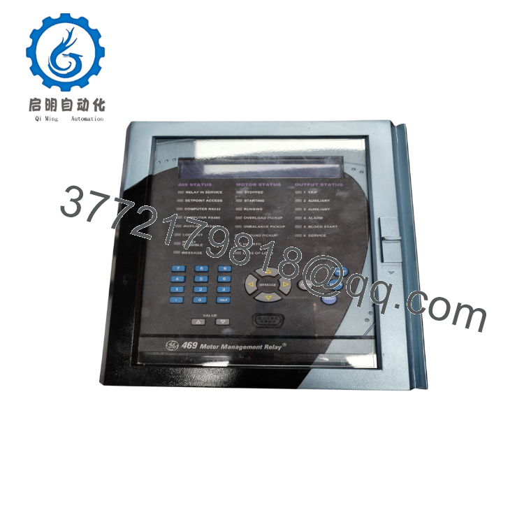
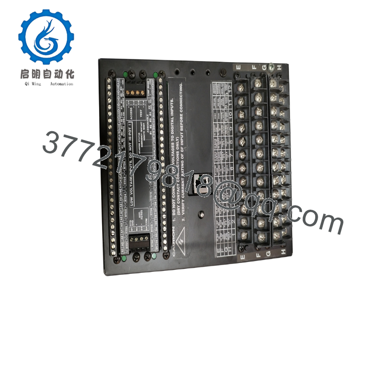
The SR469-P1-HI-A20-T is a cased version of the Multilin 469 motor management relay. It provides comprehensive protection, monitoring, diagnostics, and control for medium- and large-horsepower AC motors while supporting Ethernet integration into plant automation systems. It has been discontinued by the manufacturer, with the Multilin 869 recommended as the migration platform.
4. Product Introduction
The GE SR469-P1-HI-A20-T is a digital motor protection relay designed for medium-voltage motor applications in power generation, mining, oil and gas, water treatment, and heavy industrial facilities. It combines motor protection, metering, event recording, and communication functions within a single draw-out relay platform.
This configuration includes 1 A CT inputs, high-range control power, 4–20 mA analog outputs, and 10Base-T Ethernet for SCADA and DCS integration. Before replacement, verify firmware compatibility, CT ratios, and existing protection settings to avoid unnecessary commissioning delays.

- SR469-P1-HI-A20-T
- SR469-P1-HI-A20-T
5. Installation & Configuration Guide
Stage 1 – Pre-Installation Preparation (15 Minutes)
⚠️ Safety First
- Notify operations of the planned outage.
- Trip and isolate the motor feeder.
- Apply Lockout/Tagout procedures.
- Verify all control voltages are de-energized.
- Wait at least 5 minutes before removing the relay.
Tools Required
- ESD wrist strap
- PH1 screwdriver
- Fluke 115 multimeter
- Insulated terminal screwdriver
- Laptop with GE EnerVista 469 Setup
- Smartphone for recording wiring
Data Backup
Before removing the relay:
- Upload and save the existing settings file.
- Export event records if required.
- Record firmware revision.
- Photograph CT, VT, RTD, and digital I/O wiring.
- Record Ethernet IP address and communication settings.
Stage 2 – Removing the Old Relay (10 Minutes)
- Open the switchgear compartment.
- Disconnect auxiliary power.
- Label all terminal blocks.
- Release the draw-out mechanism.
- Remove the relay straight out without twisting.
Inspect:
- Terminal blocks
- Draw-out contacts
- Chassis connectors
- Ground connections
⚠️ Keep the original relay until commissioning has been completed successfully.
Stage 3 – Installing the New Relay (15 Minutes)
- Wear an ESD wrist strap.
- Verify the complete model:
SR469-P1-HI-A20-T
- Confirm:
- CT input rating (1 A)
- Control power (HI)
- Ethernet option
- Analog output configuration
- Insert the relay until fully seated.
- Reinstall terminal blocks.
- Restore all wiring exactly as documented.
Installation Checklist
- Model verified
- CT ratio confirmed
- Terminal blocks secured
- Ethernet connected
- Ground verified
Stage 4 – Power-On & Testing (30 Minutes)
Pre-Power Check
- Measure auxiliary control voltage.
- Verify CT circuits are closed.
- Confirm RTD wiring.
- Check Ethernet cable continuity.
Startup Procedure
- Energize the relay.
- Verify LCD startup.
- Confirm no hardware alarms.
- Connect using EnerVista software.
- Verify firmware version.
- Restore the saved settings if necessary.
- Perform secondary injection testing.
- Verify trip logic before returning the motor to service.
⚠️ Troubleshooting Note
If the relay reports communication faults after replacement, first verify Ethernet parameters and firmware compatibility before changing protection settings. Firmware revisions can affect communications and feature availability.
SOP Quality Verification
1. Inbound Inspection & Traceability
Every SR469-P1-HI-A20-T undergoes:
- OEM label verification
- Serial number recording
- Anti-counterfeit inspection
- Draw-out mechanism inspection
- Terminal inspection
Visual inspection confirms:
- No corrosion
- No cracked display
- No damaged connectors
- No repair marks
2. Live Functional Testing
Testing is performed on a dedicated GE Multilin motor protection test bench.
Verification includes:
- Power-on self-test
- LCD verification
- Ethernet communication
- RS-485 communication
- Digital input simulation
- Analog output verification
- RTD simulation
- Protection element testing
- Continuous operation exceeding 24 hours
A formal test report is generated.
Test photographs and videos are available upon request.
3. Electrical Parameter Testing
Testing includes:
- 500 V insulation resistance (>10 MΩ where applicable)
- Ground continuity verification
- Auxiliary power verification
- Analog output calibration
4. Firmware & Configuration Verification
Record:
- Firmware revision
- Hardware revision
- Ethernet configuration
- Protection settings
- CT ratio configuration
- RTD configuration
Maintain a photographic record of terminal wiring before shipment.
5. Final QC & Packaging
Final preparation includes:
- QC inspector approval
- Anti-static ESD packaging
- Protective foam inserts
- Heavy-duty corrugated carton
- QC Passed label with inspection date
Technical Pitfalls & Survival Guide
❗ Firmware Revision Mismatch
I’ve seen technicians replace an SR469 with newer firmware and spend nearly two days chasing communication alarms. The relay hardware was healthy, but the newer firmware required updated settings and communication mapping.
Always document the installed firmware before ordering a replacement.
❗ CT Secondary Rating
This model is the P1 version for 1 A CT secondary inputs.
Installing a 5 A relay into a system wired for 1 A CTs produces incorrect current measurements and can compromise motor protection.
Always verify the CT secondary rating before installation.
❗ Ethernet Configuration
The T option provides integrated 10Base-T Ethernet.
Record the relay IP address before removal. Replacing the hardware without restoring the network configuration often results in communication loss with the DCS or SCADA system.
❗ RTD Wiring
The relay supports up to 12 RTD inputs.
Never reconnect RTD cables from memory. Label every cable and photograph the wiring before removal. Misplaced RTDs can generate nuisance thermal alarms that are difficult to diagnose.
❗ Electrostatic Discharge (ESD)
The relay contains sensitive measurement electronics.
Always:
- Wear a grounded wrist strap.
- Handle the relay by its enclosure.
- Install it on an ESD-safe surface.
Keep these checks in mind and you’ll avoid most of the commissioning issues encountered during Multilin 469 replacements.
6. Frequently Asked Questions (FAQ)
Q1. What is the SR469-P1-HI-A20-T used for?
It protects and manages medium- and large-horsepower three-phase AC motors by combining thermal protection, overload protection, metering, diagnostics, event recording, and communications in one relay.
Q2. Is this relay still manufactured?
No.
The Multilin 469 has been discontinued. GE Vernova recommends the Multilin 869 as the current migration platform for most applications.
Q3. Can I replace only the relay without changing the wiring?
In many existing installations, yes. The SR draw-out construction minimizes rewiring. However, always verify the hardware revision and compatibility with your existing chassis and settings before installation. Retrofit kits are available for migration to the 869 platform.
Q4. Will removing the relay erase my motor protection settings?
Not if you’ve backed them up first.
Upload the settings using EnerVista 469 Setup before removing the relay. Restoring a verified settings file is much faster and reduces commissioning errors.
Q5. What does the model suffix mean?
- P1 – 1 A CT secondary inputs
- HI – 90–300 VDC / 70–265 VAC control power
- A20 – Four 4–20 mA analog outputs
- T – Integrated 10Base-T Ethernet communications
Q6. Why is the price often lower than the original OEM list price?
Many available units come from unused project inventory, modernization programs, or surplus spare-part stock. Before purchasing, request:
- Serial number verification
- Firmware revision
- Functional test report
- Burn-in record
- Warranty terms
Q7. What documents should I request before shipment?
For critical motor protection applications, request:
- Firmware revision report
- Functional test report
- Ethernet communication verification
- Analog output calibration record
- 24-hour burn-in report
- QC inspection report
- ESD packaging confirmation
These records help reduce commissioning risk and improve confidence when replacing legacy Multilin 469 motor management relays.



