WhatsApp: +86 16626708626
 Email:
 Phone: +86 16626708626
Description
Core Product Summary (Brand / Model / Key Attributes)
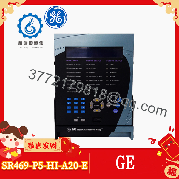
The GE SR469-P5-HI-A20-E (base relay order code 469-P5-HI-A20-E) is a digital motor management relay in the GE Multilin 469 series designed to protect, meter, and control medium and large three-phase motors and their driven mechanical equipment. Housed in an SR-series draw-out chassis, it integrates thermal overload modeling, stator differential and ground fault protection, voltage and power monitoring, and event recording inside a single panel-mounted unit.
Configured specifically to the P5-HI-A20-E order option set, this model accepts 5 A phase current transformer (CT) secondaries, operates from a wide-range high control power supply (90–300 VDC or 70–265 VAC at 48–62 Hz), provides four isolated 4–20 mA analog outputs, and features the enhanced 40-character front-panel LCD with 22 status LEDs and a local RS-232 programming port. Standard I/O includes 12 programmable RTD inputs, 9 digital inputs, 4 analog transducer inputs, 6 Form-C output relays, and RS-485 serial communications supporting Modbus RTU for configuration via EnerVista 469 Setup software.
Key Technical Specifications
| Parameter | Verified Specification |
| Manufacturer / Brand | GE Multilin (General Electric) |
| Model / Order Number | SR469-P5-HI-A20-E (Relay Unit: 469-P5-HI-A20-E) |
| Product Series | Multilin 469 Motor Management Relay |
Phase Current Inputs (P5) |
5 A phase CT secondaries (two 3-phase sets: phase metering/protection and stator differential) |
Control Power Supply (HI) |
90 to 300 VDC; 70 to 265 VAC at 48 to 62 Hz |
Analog Outputs (A20) |
4 isolated 4–20 mA analog outputs (accuracy: ±1% of full scale) |
Front Panel / Display (E) |
Enhanced 40-character LCD display, numeric/control keypad, 22 status LEDs, sealable draw-out handle |
| RTD Inputs | 12 programmable 3-wire RTD inputs (100 Ω Platinum, 100 Ω Nickel, 120 Ω Nickel, 10 Ω Copper) |
| Digital Inputs | 9 opto-isolated digital inputs (5 predefined functions + 4 assignable inputs) |
| Analog Transducer Inputs | 4 configurable inputs (individually selectable for 4–20 mA, 0–20 mA, or 0–1 mA) |
| Relay Outputs | 6 electromechanical Form-C output relays (10 ms typical operate time) |
| Communication Interfaces | Front RS-232 program port (up to 19,200 bps); Rear RS-485 ports supporting Modbus RTU (300 to 19,200 bps) |
| Event Recording | Date- and time-stamped event recorder storing up to 256 events |
| Operating / Storage Temperature | Operating: -40 °C to +60 °C (-40 °F to +140 °F); Storage: -40 °C to +80 °C (-40 °F to +185 °F) |
| Relative Humidity | Up to 90%–95% non-condensing |
| Enclosure / Terminal Ratings | Front panel IP20-X; Overvoltage Category II, Pollution Degree 2, 300 V insulation voltage; #8 ring lug terminals |
| Configuration Software | GE EnerVista 469 Setup |
Detailed Product Overview
The GE SR469-P5-HI-A20-E consolidates multi-function motor protection, process metering, and breaker/contactor control for critical industrial rotating machinery such as pumps, compressors, fans, crushers, and mills. Rather than wiring separate thermal overload relays, RTD temperature scanners, current/power transducers, and fault annunciators, the relay computes protection decisions directly from phase currents, line/phase voltages, and embedded winding or bearing temperature sensors.
Its thermal protection model combines motor current history with negative-sequence current biasing—accounting for additional rotor heating caused by supply voltage or current unbalance—and temperature feedback from up to 12 programmable RTD inputs. Each RTD channel supports independent alarm, high alarm, and trip thresholds, trip voting, and open/short sensor failure detection. In addition to thermal overload, locked-rotor/stall, and start-inhibit protection, the relay includes two sets of three-phase CT inputs to support stator differential protection alongside ground fault, over/undervoltage, phase reversal, frequency, and mechanical jam/undercurrent elements.
The SR469-P5-HI- order code defines the exact hardware option package. The P5 option matches standard 5 A secondary phase CTs, HI enables operation across universal substation DC or AC control power rails, A20 supplies four programmable 4–20 mA analog outputs for transmitting metered values (such as motor load, thermal capacity used, or hotspot RTD temperature) directly to a PLC or DCS analog input card, and E equips the relay with the enhanced 40-character LCD interface. Note that this standard -E variant provides RS-232 and RS-485 Modbus RTU serial communications rather than an embedded 10Base-T Ethernet interface (which is designated by the -T order suffix).
For commissioning and panel maintenance, the relay uses a draw-out construction that allows the active electronic chassis to slide out of its fixed terminal case without disturbing field CT, PT, RTD, or trip-coil wiring. Built-in simulation mode lets technicians inject virtual currents, voltages, RTD temperatures, and analog signals to verify trip logic, Form-C relay actuation, and SCADA register mapping before energizing the motor.
SR469-P5-HI-A20-E
Engineering Selection Highlights
- Exact order-code verification (
P5-HI-A20-E) → Confirms 5 A phase CT inputs (not 1 AP1), high-range 70–265 VAC / 90–300 VDC control power (not low-rangeLO), four 4–20 mA analog outputs (not 0–1 mAA1), and the enhanced display without embedded Ethernet (-Evs.-T). - Two sets of 3-phase 5 A CT inputs → Supports both standard phase overcurrent/metering functions and dedicated three-phase stator differential protection on medium- and large-horsepower motors.
- 12 field-programmable RTD channels → Monitors stator windings, motor bearings, and ambient/coolant temperatures across Pt100, Ni100, Ni120, or Cu10 sensors with configurable voting to prevent nuisance trips from a single failed sensor.
- Four isolated 4–20 mA outputs + RS-485 Modbus RTU → Enables simultaneous hardwired analog trending to a DCS/PLC and serial register polling over Modbus RTU.
- Draw-out case architecture → Allows rapid chassis removal or replacement using the sealable front handle while leaving rear #8 ring-lug field wiring intact.
- Built-in pre-trip and fault simulation mode → Simplifies setpoint verification and trip-circuit testing during commissioning without requiring primary current injection.
System Compatibility & Integration Requirements
| Item / Dependency | Verified Compatibility or Requirement | Practical Note |
| Phase Current Transformers (CTs) | 5 A secondary CTs (P5 option) |
Must match 5 A secondary CTs; 1 A secondary CT circuits require the P1 hardware variant. |
| Control Power Source | 70–265 VAC (48–62 Hz) or 90–300 VDC (HI option) |
Verify station battery or control transformer voltage falls within the HI supply range before energizing. |
| RTD Temperature Sensors | 3-wire 100 Ω Platinum, 100 Ω Nickel, 120 Ω Nickel, or 10 Ω Copper | Each of the 12 RTD inputs can be individually programmed for sensor type in setpoints. |
| Analog Control / SCADA I/O | 4 × 4–20 mA outputs (A20) and 4 × 0–1 / 0–20 / 4–20 mA inputs |
Ensure receiving PLC/DCS analog input cards accept active/isolated 4–20 mA signals. |
| Serial Host / PLC / DCS Network | RS-485 2-wire serial bus using Modbus RTU (300–19,200 bps) | If native 10Base-T Modbus TCP Ethernet is required, verify whether a -T option relay or external serial-to-Ethernet gateway is needed. |
| Configuration & Commissioning Software | GE EnerVista 469 Setup (via front RS-232 or rear RS-485) | Front 9-pin RS-232 port defaults to 9600 bps (configurable up to 19,200 bps) for local PC connection. |
| Mounting Enclosure / Chassis | Multilin SR469 Draw-Out Case (SR469-CASE) |
Confirm whether the replacement order includes both the draw-out relay unit and fixed rear case or the draw-out relay module only. |
Dimensions, Mounting & Connection Notes
- Physical Dimensions & Weight: Approximate overall dimensions are 8.52 in × 8.80 in × 9.93 in (H × W × D), with a unit weight of approximately 7.7 kg (17 lbs) when assembled with the draw-out case.
- Panel Cutout & Mounting: Semi-flush panel cutout installation utilizing the SR-series draw-out case; ensure front clearance is maintained to unlatch and withdraw the relay chassis via the front pull handle.
- Rear Field Wiring Terminations: Uses barrier terminal blocks accepting #8 ring lugs with standard 10 AWG wire for CT, VT, control power, digital/analog I/O, and Form-C relay contact connections.
- Current Transformer Safety: Verify that the rear case automatic CT shorting mechanism is intact and clean before withdrawing the relay unit from an energized CT circuit.
- Environmental Limits: Rated for -40 °C to +60 °C ambient operating temperature and up to 90%–95% non-condensing relative humidity; note that the standard
-Emodel does not include the-Hharsh-environment conformal coating suffix.
FAQ
What is the GE -P5-HI-? The GE SR469-P5-HI-A20-E is a digital motor management relay in the GE Multilin 469 series designed to protect, monitor, and control medium and large three-phase motors.
What dach cod stand for? identifies the cased Multilin 469 relay family, P5 specifies 5 A phase CT secondaries, HI designates the 90–300 VDC / 70–265 VAC control power supply, A20 indicates four 4–20 mA analog outputs, and E specifies the enhanced 40-character front-panel LCD.
the have an Ethernet port? No. The -E suffix designates the enhanced display option with RS-232 and RS-485 Modbus RTU serial communication ports; factory 10Base-T Ethernet is provided on -T option models.
How many RTD inputs and output relays are built into this model? It provides 12 programmable 3-wire RTD inputs (supporting Pt100, Ni100, Ni120, and Cu10 sensors) and 6 electromechanical Form-C output relays.
What control power voltage is required for the HI power supply option? The HI power supply operates on 90 to 300 VDC or 70 to 265 VAC at 48 to 62 Hz.
Which software is used to program and retrieve event records from the SR469-P5-HI-A20-E? Setpoint configuration, firmware updates, metering views, and 256-event log retrieval are performed using GE EnerVista 469 Setup software connected through the front RS-232 port or rear RS-485 network.
Verification & Troubleshooting Notes
- Control Power & Self-Test Verification: Confirm incoming control power at the rear terminals measures between 70–265 VAC or 90–300 VDC; upon power-up, verify that the
469 IN SERVICEstatus indicator illuminates and no internal self-test error appears on the 40-character LCD. - CT & VT Secondary Safety Check: Before sliding the draw-out relay chassis out of its case during maintenance, verify breaker/contactor isolation and confirm the rear case CT shorting bars properly engage to prevent open-circuited current transformer hazards.
- RTD Open / Short Diagnostics: If an RTD trouble alarm occurs, inspect the LCD diagnostics or EnerVista 469 actual values screen to identify which of the 12 channels is reporting an open or short circuit, and verify 3-wire lead resistance balance and programmed sensor type (
Pt100,Ni100,Ni120, orCu10). - RS-232 / RS-485 Communication Checks: If EnerVista 469 Setup fails to connect via the front RS-232 port, verify that the PC serial port matches the relay’s configured baud rate (9600 bps default, up to 19,200 bps) and Modbus slave address.
- Simulation Mode Restoration: When using the built-in simulation feature to test trip relays and 4–20 mA outputs during commissioning, confirm that simulation mode is explicitly disabled afterward so the relay returns to live CT/VT/RTD protection.