
 WhatsApp: +86 16626708626
 Email:
  Phone: +86 16626708626
Description
3. Key Technical Specifications
| Parameter | Value |
|---|---|
| Manufacturer | GE Multilin |
| Model | SR750-P1-G1-S1-HI-A20-R-E-H |
| Product Family | Multilin 750 Feeder Management Relay |
| Product Type | Digital Feeder Protection Relay |
| Phase CT Inputs | 1 A (P1) |
| Zero-Sequence CT Input | 1 A (G1) |
| Sensitive Ground CT Input | 1 A (S1) |
| Control Power | 88–300 VDC or 70–265 VAC, 48–62 Hz (HI) |
| Analog Outputs | Eight 4–20 mA outputs (A20) |
| Breaker Status LED | Red breaker closed indicator (R) |
| Display | Enhanced LCD display and keypad (E) |
| Communications | RS-485 Modbus RTU; Ethernet available on enhanced models |
| Configuration Software | GE EnerVista 750 Setup |
| Protection Functions | Phase OC, Ground OC, Directional, Frequency, Voltage, Breaker Failure, Auto Reclose, Metering |
| Event Recorder | Sequence of Events and Oscillography |
| Mounting | Draw-out case |
The SR750 is a microprocessor-based feeder management relay intended for protection, control, metering, automation, and diagnostics of medium-voltage distribution feeders in utility and industrial power systems.
4. Product Introduction
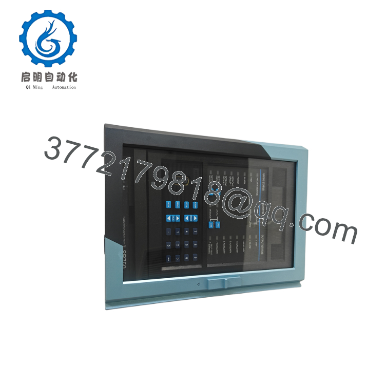
The GE Multilin SR750-P1-G1-S1-HI-A20-R-E-H is a feeder management relay designed to protect medium-voltage distribution circuits against phase, ground, and abnormal system conditions while providing comprehensive metering, event recording, and automation functions. It is widely deployed in substations, industrial switchgear, mining facilities, and power generation plants.
This configuration includes 1 A phase and ground CT inputs, high-range auxiliary power, eight 4–20 mA analog outputs, and the enhanced display. Before replacing an existing relay, verify firmware revision, communication configuration, CT ratios, and protection settings to maintain coordination with upstream and downstream devices.

- SR750-P1-G1-S1-HI-A20-R-E-H
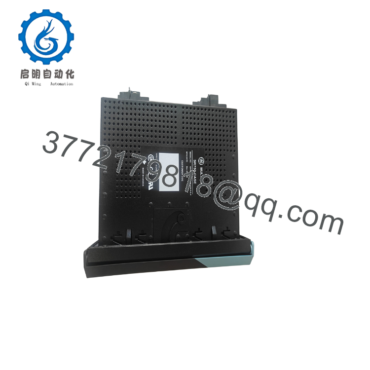
- SR750-P1-G1-S1-HI-A20-R-E-H
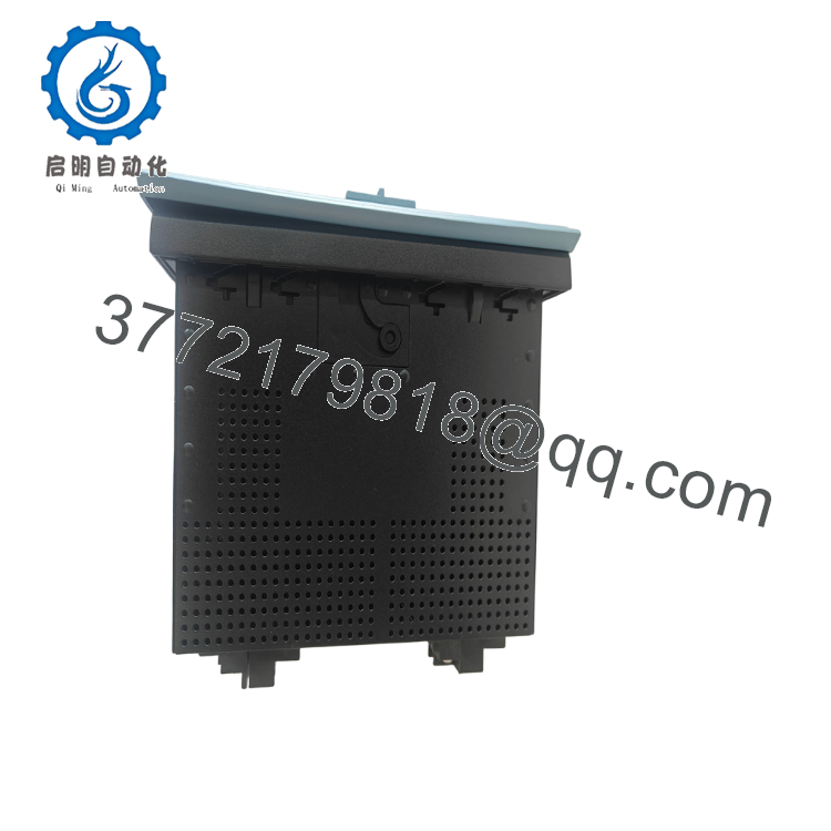
- SR750-P1-G1-S1-HI-A20-R-E-H
5. Installation & Configuration Guide
Stage 1 – Pre-Installation Preparation (15 Minutes)
⚠️ Safety First
- Notify operations of the planned feeder outage.
- Open and isolate the feeder breaker.
- Apply Lockout/Tagout procedures.
- Verify auxiliary power is removed.
- Wait at least 5 minutes before handling the relay.
Tools Required
- Grounded ESD wrist strap
- PH1 screwdriver
- Fluke 115 digital multimeter
- Secondary injection test set
- Laptop with GE EnerVista 750 Setup
- Smartphone for wiring documentation
Data Backup
Before removing the relay:
- Upload and save the complete settings file.
- Export event and fault records.
- Record firmware version.
- Document CT and VT ratios.
- Photograph all terminal wiring.
- Record Ethernet and RS-485 communication parameters.
Stage 2 – Removing the Old Relay (10 Minutes)
- Open the relay compartment.
- Disconnect auxiliary control power.
- Label every terminal block.
- Release the draw-out mechanism.
- Remove the relay evenly to avoid damaging the rear connectors.
Inspect:
- Draw-out contacts
- Rear connector pins
- Terminal blocks
- Ground connections
⚠️ Retain the original relay until all protection functions have been verified.
Stage 3 – Installing the New Relay (15 Minutes)
- Wear an ESD wrist strap.
- Verify the model:
SR750-P1-G1-S1-HI-A20-R-E-H
- Confirm:
- 1 A CT inputs
- High-voltage auxiliary power
- Analog output option
- Display version
- Hardware revision
- Insert the relay fully into the case.
- Secure the locking mechanism.
- Restore all wiring exactly as documented.
Installation Checklist
- Model verified
- CT ratios confirmed
- Wiring secured
- Ground verified
- Communication ports connected
Stage 4 – Power-On & Testing (30 Minutes)
Pre-Power Check
- Measure auxiliary voltage.
- Verify CT circuits remain shorted until energized.
- Confirm VT wiring.
- Inspect communication wiring.
Startup Procedure
- Apply auxiliary power.
- Verify normal LCD startup.
- Check for self-diagnostic alarms.
- Connect using EnerVista 750.
- Verify firmware revision.
- Restore the saved configuration if required.
- Perform secondary current injection testing.
- Verify trip logic and breaker control before returning the feeder to service.
⚠️ Troubleshooting Note
A solid relay health alarm immediately after replacement frequently indicates a firmware or settings mismatch rather than defective hardware. Verify firmware compatibility before modifying protection settings.
6. Frequently Asked Questions (FAQ)
Q1. What is the SR750-P1-G1-S1-HI-A20-R-E-H used for?
It is a digital feeder management relay used to protect, monitor, and control medium-voltage distribution feeders in utility substations and industrial electrical systems. It combines protection, automation, metering, and event recording in a single device.
Q2. Is this relay still manufactured?
No. The SR750 is considered a legacy Multilin platform. Availability is generally limited to new surplus inventory or professionally tested refurbished units.
Q3. What do the option codes mean?
The verified option codes are:
- P1 – 1 A phase current inputs
- G1 – 1 A zero-sequence current input
- S1 – 1 A sensitive ground current input
- HI – 88–300 VDC / 70–265 VAC auxiliary power
- A20 – Eight 4–20 mA analog outputs
- R – Red breaker-closed LED
- E – Enhanced LCD display and keypad
The trailing H suffix is not publicly documented. Confirm its meaning with the relay nameplate or original purchase documentation before ordering.
Q4. Can I replace the relay without changing my protection settings?
Only if the replacement has compatible firmware and hardware. Always upload the existing settings before removal and verify every protection element after downloading the configuration into the replacement relay.
Q5. Does this relay support SCADA integration?
Yes. The SR750 platform supports industrial communications including Modbus RTU, and enhanced configurations provide Ethernet capabilities for integration with SCADA and energy management systems. Verify the communication hardware installed on your specific unit.
Q6. Why is surplus inventory usually less expensive than OEM pricing?
Many legacy relays become available through substation upgrades, project cancellations, or unused utility spare inventories. Request serial-number verification, firmware information, functional test reports, and warranty details before purchase.
Q7. What documentation should I request before shipment?
For critical feeder protection applications, request:
- Firmware revision report
- Complete hardware option verification
- Functional test report
- Secondary injection test results
- Communication verification
- 24-hour burn-in report
- QC inspection report
- ESD packaging confirmation
These documents help minimize commissioning time and reduce the risk of unexpected protection or communication issues after installation.



