
 WhatsApp: +86 16626708626
 Email:
  Phone: +86 16626708626
Description
3. Key Technical Specifications
| Parameter | Value |
|---|---|
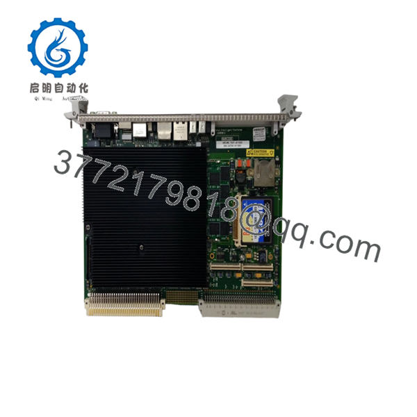
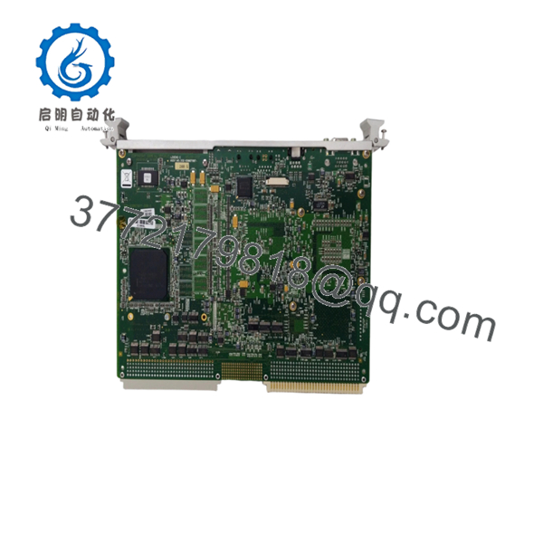
| Model Number | VME7807RC350-00780-411000 |
| Manufacturer | GE Fanuc Automation |
| Product Type | VMEbus Digital Input Module |
| Input Channels | 64 optically isolated digital inputs |
| Isolation Rating | 1,500 VDC channel-to-channel and channel-to-VMEbus |
| Input Voltage Range | 5-60 VDC or 110-240 VAC |
| Event Functions | COS (Change of State), SOE (Sequence of Events) |
| Pulse Accumulation | Up to 65,535 counts per channel |
| Debounce Time | Programmable, 1.25 ms to 1.024 s |
| Time Stamping | Supported |
| Surge Protection | ANSI/IEEE C37.90.1 compliant with suppression panel |
| Bus Interface | VMEbus |
| Application | Power systems, process control, industrial automation |
| Operating Environment | Industrial control cabinets and VME racks |
| Product Status | Discontinued by OEM |
Technical specifications summarized from available legacy GE Fanuc VME documentation and distributor references. Verify exact revision-specific values before installation.
4. Product Introduction
The GE VME7807RC350-00780-411000 is a 64-channel isolated digital input module designed for VMEbus-based control and monitoring systems. It is commonly found in power generation, substation automation, process control, and legacy industrial control platforms requiring high-density discrete input acquisition.
A key characteristic of this module is its combination of optical isolation, Sequence of Events (SOE) recording, Change of State (COS) detection, pulse accumulation, and programmable debounce filtering. In field deployments of legacy GE Fanuc VME systems, these features were frequently used for breaker monitoring, alarm logging, and high-speed event capture where timing accuracy mattered.

- VME7807RC350-00780-411000
- VME7807RC350-00780-411000
5. Installation & Configuration Guide
Stage 1: Pre-Installation Preparation (10 Minutes)
⚠️ Safety First
- Notify operations and obtain shutdown approval.
- Verify the process is in a safe state.
- Apply Lockout/Tagout (LOTO).
- Remove rack power.
- Wait at least 5 minutes for capacitor discharge.
Tools Required
- ESD wrist strap
- PH1 screwdriver
- Fluke 115 multimeter
- Wire labels
- Smartphone for documentation
- Flashlight for rack inspection
Data Backup
- Export controller configuration files.
- Record rack slot location.
- Document node addresses.
- Photograph all terminal wiring.
- Photograph DIP switches and jumper settings.
- Save existing SOE/COS configuration parameters if accessible.
Stage 2: Removing the Old Module (5 Minutes)
- Remove front panel cover if fitted.
- Label all field wiring before disconnecting.
- Disconnect terminal blocks carefully.
- Release VME retention screws and extraction levers.
- Pull the module straight out.
⚠️ Note
Keep the old module nearby until the replacement passes operational testing.
Inspection Checklist
- Backplane connectors clean
- No bent VME pins
- No corrosion
- No conductive dust accumulation
Stage 3: Installing the New Module (10 Minutes)
Steps
- Wear an ESD wrist strap and verify grounding.
- Verify model number matches exactly:
- VME7807RC350-00780-411000
- Configuration Clone (Critical)
- Copy all DIP switch positions.
- Match node addressing.
- Match termination settings.
- Insert module evenly into guide rails.
- Seat fully into backplane connector.
- Tighten retention hardware.
- Reconnect field wiring.
Self-Checklist
- Model number verified
- DIP switches duplicated
- Wiring secured
- Retention screws tightened
- Module fully seated
Stage 4: Power-On & Testing (10 Minutes)
Pre-Power Check
- Measure 24 V supply rails.
- Check for shorts using a multimeter.
- Verify cabinet grounding.
Power-Up Sequence
- Energize rack power only.
- Observe module LEDs.
- Confirm normal startup indications.
- Verify VMEbus recognition by host processor.
- Restore application configuration if required.
- Simulate several digital input points.
- Verify COS and SOE reporting.
- Confirm timestamps are being generated correctly.
⚠️ Troubleshooting Note
- Solid fault LED: Check firmware compatibility and rack configuration.
- No communication: Verify slot assignment and VMEbus addressing.
- Missing inputs: Inspect suppression panel and field wiring.
- Intermittent alarms: Check debounce settings and shielding practices.
SOP Quality Transparency
1. Inbound Inspection & Traceability
Every incoming VME7807RC350-00780-411000 undergoes:
- OEM label verification
- Serial number recording
- Anti-counterfeit inspection
- Visual inspection for:
- Corrosion
- Scratches
- Rework marks
- UV discoloration
- Accessory audit when available
2. Live Functional Testing
Tested on a genuine VMEbus test rack.
Procedures include:
- Power-on self-test
- LED verification
- VMEbus communication validation
- Digital input simulation across multiple channels
- COS and SOE verification
- Continuous load operation exceeding 24 hours
- Thermal monitoring
A formal test report can be generated upon request.
3. Electrical Parameter Testing
- 500 V Megger insulation test (>10 MΩ)
- Ground continuity verification
- Power rail measurement
- Hipot testing where applicable
4. Firmware & Configuration Verification
- Firmware revision documented
- Switch and jumper settings photographed
- Configuration archived before shipment
5. Final QC & Packaging
- QC inspector sign-off
- Anti-static ESD packaging
- Bubble-wrap protection
- Heavy-duty corrugated carton
- QC Passed label with inspection date
Test photos and videos are available upon request.
Technical Pitfall & Survival Guide
❗ Firmware Revision Mismatch
I’ve seen technicians replace a working module only to spend two days chasing communication faults. The replacement board carried a different firmware revision and the host software rejected it.
Avoidance:
- Record firmware revision before removal.
- Request matching firmware ranges when ordering.
- Verify compatibility with the existing VME controller.
❗ DIP Switch / Jumper Misconfiguration
This is the most common rookie mistake, but experienced engineers make it too.
Take a picture before you pull it. I can’t stress this enough.
Avoidance:
- Photograph every switch bank.
- Match node addresses exactly.
- Verify termination resistor settings.
❗ Terminal Block / Wiring Incompatibility
Legacy VME installations often contain undocumented field modifications.
I’ve opened cabinets where two identical-looking boards had different wiring assignments because of historical upgrades.
Avoidance:
- Verify wiring diagrams.
- Label every conductor.
- Check shield termination points.
❗ Power Draw Calculations
A replacement module may not be the only load on the rack.
I’ve seen VME power supplies running at 95% capacity for years. One additional board pushed them over the edge and caused random resets.
Avoidance:
- Calculate total rack consumption.
- Maintain at least a 20% power margin.
- Verify backplane current ratings.
❗ Electrostatic Discharge (ESD)
I once watched an engineer handle a board during winter shutdown work without an ESD strap. The module failed immediately after power-up.
That mistake cost more than the maintenance outage itself.
Avoidance:
- Use a grounded wrist strap.
- Work on an ESD mat.
- Keep modules in anti-static packaging until installation.
Keep these checks in mind and you’ll save yourself 90% of typical rework time.
6. Frequently Asked Questions (FAQ)
Q1. Can I hot-swap this module under power?
No. Treat this module as non-hot-swappable unless the entire system architecture explicitly supports live insertion.
Pulling a VME module under power can corrupt bus communications or damage backplane connectors. Shut down the rack first.
Q2. Is VME7807RC350-00780-411000 obsolete?
Yes.
GE Fanuc no longer manufactures this module. Most available inventory today comes from surplus stock, strategic spares inventories, or professionally tested refurbished units.
Q3. Is the product genuinely new?
Availability varies by inventory source.
Typical conditions include:
- New Original (New Surplus)
- Factory-Sealed Surplus
- Refurbished (Tested)
Request actual photographs and serial numbers before purchase.
Q4. Will I lose my control logic when replacing this module?
Normally no.
This module functions as a digital input interface rather than a system CPU. Logic generally resides in the controller or host processor.
However, document all configuration parameters before removal because event-processing settings may need to be recreated.
Q5. What should I check before ordering a replacement?
Verify:
- Full model number
- Hardware revision
- Firmware revision
- Slot location
- Input voltage requirements
- Suppression panel compatibility
Many downtime incidents start because only the base model number was checked.
Q6. What is the most common startup problem after replacement?
Firmware and configuration mismatches.
In field service work, communication faults caused by incorrect DIP switch settings occur far more often than actual hardware failures.
Take detailed photos before removal.
Q7. Why is the price often lower than historical OEM pricing?
Because these units are no longer factory-produced.
Most inventory comes from surplus industrial stock, decommissioned systems, or excess spare-part inventories. Pricing reflects market availability rather than original OEM list pricing. Always verify testing documentation and warranty coverage before purchase.


