
 WhatsApp: +86 16626708626
 Email:
  Phone: +86 16626708626
Description
Key Technical Specifications
| Parameter | Specification Value |
| Input Channels | 32 Differential or 64 Single-Ended (jumper configurable) |
| ADC Resolution | 12-Bit Binary |
| Form Factor | 6U Single-Slot VMEbus |
| Input Voltage Ranges | ±10 V, ±5 V, 0 to 10 V, 0 to +5 V (software selectable) |
| Conversion Rate | Up to 100 kHz aggregate scanning speed |
| Data Buffer | Onboard FIFO memory buffer for continuous data streaming |
| Inherent Accuracy | ±0.05% of Full Scale Range (FSR) |
| Overvoltage Protection | ±30 V continuous on all input channels |
| Current Consumption | +5 V (approx. 2.8 A), +12 V (approx. 0.2 A) |
| Operating Temperature | 0 to +65 °C (forced-air cooling recommended) |
Product Introduction & Supply Chain Strategy
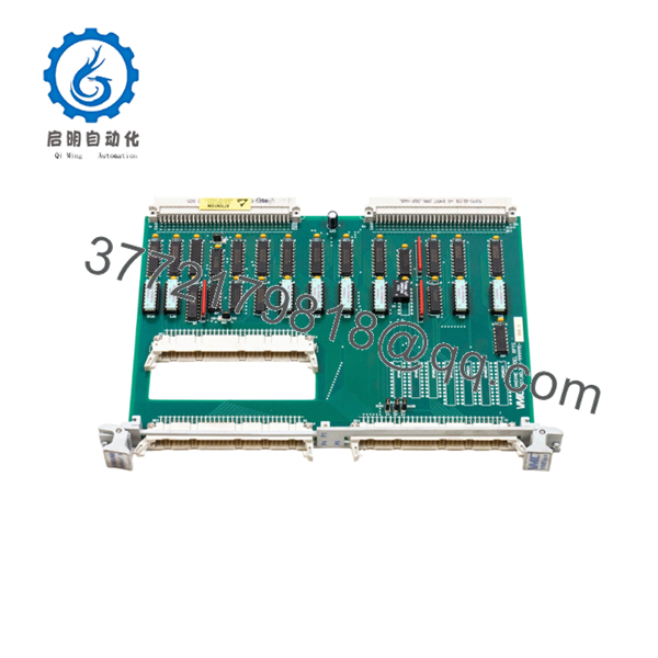
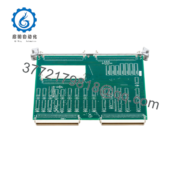
The GE VMIC 332-999995-000 D is a commercial-grade 6U VMEbus analog input board designed for high-density, real-time data acquisition. Utilized extensively in legacy gas turbine control configurations, defense flight simulators, and high-speed process control loops, this module converts external analog sensor signals into precise 12-bit digital registers. Its localized FIFO buffer and scanning logic allow the host VME processor to offload low-level signal sampling, mitigating data bottlenecks and maintaining tight deterministic cycle times.
From a procurement and maintenance optimization standpoint, this specific “D” revision board represents an increasingly scarce, obsolete asset. Hardware failures in high-speed processing loops instantly stop production lines or simulation arrays, driving massive stock-out costs. Sourcing this unit as a certified New Surplus module ensures that your facility bypasses the high-failure risks typical of refurbished circuit boards—such as dried electrolytic capacitors or brittle trace solder joint cracks. Maintaining a dedicated, on-site buffer stock of this module provides plant managers with instant risk insulation and lower Total Cost of Ownership (TCO) compared to forcing a premature, high-risk system migration.

- VMIC 332-999995-000 D
- VMIC 332-999995-000 D
Installation & Configuration Guide
Stage 1: Pre-Installation (Prep & Safety)
- Completely isolate the target VME chassis from all AC/DC power sources. Follow standard lock-out/tag-out (LOTO) guidelines.
- Put on an ESD-safe wrist strap connected to a verified chassis ground point to avoid static discharge damage to the high-impedance input instrumentation amplifiers.
- Review and map the hardware jumper configurations (such as the base address selection and differential vs. single-ended input routing) on the failed board before extraction.
- Verify that the incoming New Surplus unit’s DIP switches and jumpers are set identically to match your specific plant control program.
Stage 2: Removal
- Unfasten the front-panel captive screws holding the top and bottom injector/ejector handles in place.
- Carefully disconnect all front-panel field wiring harnesses, noting the exact pin designations to prevent signal crossovers during re-termination.
- Push both the upper and lower ejector handles outward at the same time to unseat the card from the backplane J1/J2 slots.
- Smoothly pull the board outward along the chassis card guides. Immediately place the pulled module into a static-shielding bag.
Stage 3: Installation (Clone & Seat)
- Double-check that no backplane pins on the VME chassis slot are bent or contaminated with dust.
- Slide the configured 332-999995-000 D module into the target slot along the guide tracks.
- Push the board inward firmly until the ejector levers contact the chassis frame, then pivot both levers inward until the front panel sits flush.
- Fasten the captive retaining screws on the front panel to guarantee ground continuity and structural stability against industrial vibration.
Stage 4: Power-On & Testing
- Re-terminate the analog input field wiring harnesses into the front panel high-density connector.
- Remove LOTO devices and apply system power to the VME chassis assembly.
- Monitor the module’s diagnostic LED indicators. The onboard initialization self-test must complete successfully, leaving the fault indicators clear and the active status indicators illuminated.
- Run your system’s loop calibration routine to ensure the field sensor inputs match the expected values in the processor’s data register tables.
Firmware/Software Versions & Upgrade Notes
The VMIC 332-999995-000 D uses a static, hardwired register map that communicates with host operating systems via the standard VMEbus memory space. Because it relies on hardware-level programming (DIP switch addressing), it does not contain field-flashable operating system firmware.
⚠️ CRITICAL INTEGRATION WARNING: Ensure your software’s driver base address matches the physical jumper configuration exactly. A mismatch between the driver’s memory allocation and the module’s physical jumpers will trigger an instantaneous VME Bus Error (BERR), causing the host CPU to halt immediately.
If replacing an older revision (e.g., Revision A or B) with this Revision D module, check that your system’s driver allows for the precise analog settling time required by the newer component layout to avoid data skew across adjacent multiplexed channels.
Frequently Asked Questions (FAQ)
What distinguishes “New Surplus” from a “Refurbished” VMIC board?
Our New Surplus inventory consists exclusively of unused, pristine hardware sourced from factory overstock, cancelled projects, or strategic corporate reserves. Unlike refurbished modules, which are often recovered from decommissioned industrial environments and patched up cosmetically, this board features zero component wear, zero thermal degradation, and original factory insulation values. This delivers a complete 10-to-15-year operational life expectancy.
Why is the exact “D” revision code at the end of the model string important?
Revision codes in VMIC legacy modules indicate minor schematic updates, filter optimizations, or component changes implemented during production. Inserting an incompatible board revision can result in calibration drift or bus timing errors within highly sensitive real-time loops. This Revision D unit guarantees exact electrical compatibility if your system parameters specify this exact build configuration.
Can this analog input module be replaced while the VME chassis is live?
No. Standard VMEbus specifications do not support live insertion or removal. Attempting to pull or insert the 332-999995-000 D while power is applied to the backplane can cause transient voltage spikes across the data bus, risking severe logic damage to this module and surrounding processing units on the rack. Always completely power down the system before handling.
How do I switch the board between 32 differential and 64 single-ended modes?
Channel configuration is managed via a dedicated block of physical hardware jumpers located directly on the PCB. Differential mode uses two distinct input lines per signal to cancel common-mode noise, while single-ended mode routes signals relative to a shared board ground. Refer to your existing wiring schematic to match your current system configuration exactly before installation.
Does this product come with functional testing verification?
Yes. Every New Surplus item undergoes an extensive inbound physical and electrical inspection process inside our ESD-controlled facility. We verify structural pin alignment, check basic power rail resistance to ensure no short circuits exist, and confirm that the component matches original factory physical specifications prior to secure packaging and shipment.


