
 WhatsApp: +86 16626708626
 Email:
  Phone: +86 16626708626
Description
Key Technical Specifications
| Parameter | Specification Value |
| Input Channels | 64 non-isolated or isolated discrete inputs (grouped in banks) |
| Nominal Input Voltage | 24 VDC (compatible with 5 VDC to 48 VDC logic ranges based on jumper configuration) |
| Form Factor | 6U Single-Slot VMEbus |
| Addressing Mode | A16 or A24 short I/O space (jumper selectable) |
| Built-In Test (BIT) | Software-controlled internal loopback testing for 100% channel verification |
| Input Filter Time Constant | 1.2 ms standard hardware low-pass filter |
| Isolation Rating | Optical isolation up to 1,500 V RMS (field-to-logic) |
| Current Draw | +5 V (approx. 1.5 A maximum) |
| Operating Temperature | 0 to +60 °C (requires forced-air chassis cooling) |
| Front Panel Interface | High-density P3/P4 multi-pin connectors |
Product Introduction & Supply Chain Strategy
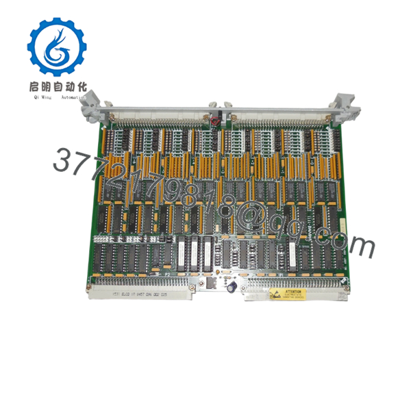
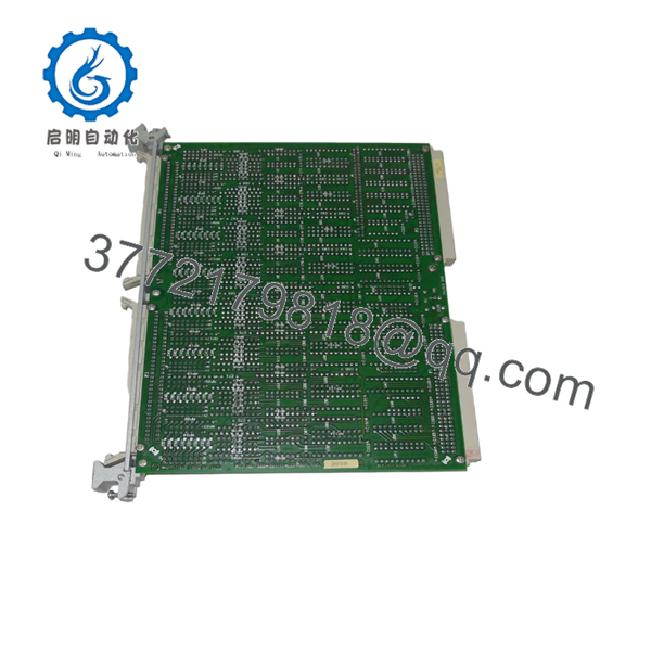
The GE VMIC VMIVME-1111 Assembly 332-001111-010D is a commercial-grade, high-density 6U VMEbus discrete digital input module. Featuring 64 individual channels, this board is a staple in legacy power generation control architectures, flight simulation logic arrays, and heavy manufacturing process automation. What sets the VMIVME-1111 apart is its integrated Built-In Test (BIT) logic, which enables real-time software diagnostics to simulate input transitions, allowing the host VME processor to verify full board functionality without disconnecting field wiring.
As an obsolete component that has reached full End-of-Life (EOL) status, sourcing this exact module assembly presents a major operational bottleneck for maintenance teams. Opting for a certified New Surplus board rather than a used or refurbished alternative guarantees uncompromised electrical isolation barriers and eliminates the risks of degraded optical couplers or dried capacitors. Securing this exact “010D” revision to place in on-site buffer stock dramatically reduces your plant’s exposure to catastrophic, multi-day stock-out events, maintaining total system uptime and minimizing the Total Cost of Ownership (TCO).

- VMIC VMIVME 1111 assy 332-001111-010D
- VMIC VMIVME 1111 assy 332-001111-010D
Installation & Configuration Guide
Stage 1: Pre-Installation (Prep & Safety)
- Completely power down the VMEbus rack enclosure. Enforce strict lock-out/tag-out (LOTO) protocols.
- Put on a grounded static-dissipative ESD wrist strap connected to an unpainted metal surface on the chassis.
- Review the physical jumper blocks on the failed board (including VME address mapping, interrupt levels, and input voltage selection).
- Configure the jumper patterns on the incoming New Surplus 332-001111-010D module to match the legacy board configuration exactly.
Stage 2: Removal
- Unscrew the front panel upper and lower captive retention screws.
- Carefully unplug the high-density digital input connector blocks from the front panel interface, ensuring the wiring harnesses remain labeled.
- Push the top and bottom ejector/injector wings outward simultaneously to break the backplane connection seal.
- Extract the card straight along the plastic guide channels and slide it directly into an ESD-protective bag.
Stage 3: Installation (Clone & Seat)
- Examine the backplane J1/J2 card slot for debris or bent contact points before inserting the card.
- Align the board edges with the top and bottom slot tracks inside the enclosure.
- Push the module inward firmly until the ejector levers contact the outer chassis rim, then pivot the levers inward to anchor the board contacts into the backplane.
- Hand-tighten the front-panel captive retention screws to establish proper chassis grounding.
Stage 4: Power-On & Testing
- Reattach the external discrete I/O signal cables to the front panel connectors.
- Remove all LOTO blocks and apply operational power to the VMEbus chassis.
- Observe the initialization LED pattern on the front plate; the system fault light must clear once initial self-checks finish.
- Execute the system software’s built-in test macro to run a digital loopback pass, confirming the host controller reads all 64 data bits correctly.
Firmware/Software Versions & Upgrade Notes
The VMIVME-1111 332-001111-010D operates using direct memory-mapped register blocks within the VME short I/O space (A16/A24 addressing). Consequently, the board lacks field-programmable flash microcode or firmware updates.
⚠️ CRITICAL INTEGRATION WARNING: The “010D” suffix represents a distinct hardware assembly revision that dictates specific timing constants for the optoisolator circuitry and input low-pass filters.
If replacing an older revision (such as an early assembly generation with different low-pass filter settings), ensure your host software driver’s polling frequency accommodates the 1.2 ms hardware debounce delay inherent to this revision. Failure to check driver timing compatibility can cause intermittent missed state transitions during high-speed, real-time discrete logic scanning cycles.
Frequently Asked Questions (FAQ)
What makes this “New Surplus” board better than a lower-cost refurbished unit?
Our New Surplus inventory consists exclusively of unused, pristine hardware sourced from corporate spares or factory overstock. Refurbished discrete boards are prone to latent damage, particularly degraded optoisolators that lose their switching speed over years of high-temperature service. This New Surplus board guarantees original OEM-level signal response times and isolation metrics, preventing unexpected production line trips.
Can this discrete digital input module be hot-swapped while the rack is live?
No. The legacy VMEbus specification utilized by the VMIVME-1111 does not accommodate hot insertion or removal. Attempting to pull or slide the module into a live rack can generate voltage arcs across the power pins, which can permanently damage the onboard VME bus interface chip or fault out other critical I/O cards sharing the backplane data lines.
How does the Built-In Test (BIT) loopback feature function on this card?
The card contains a software-activated internal diagnostic loopback circuit. When triggered by the control program, the board disconnects its internal processing logic from the active field inputs and simulates an internal test pattern. This allows you to verify the integrity of the board’s internal logic gates and buffers without needing external physical input simulation tools.
What signal voltage level does the “010D” hardware assembly require?
While nominal 24 VDC logic is standard for this assembly configuration, the board’s individual input response threshold is dictated by onboard hardware resistor networks and jumper arrays. Always match the jumper positions on the PCB surface with your system’s field excitation voltage source before powering on the device.
Does the module require periodic calibration or field alignment?
No. The VMIVME-1111 is a purely digital discrete input module that deals entirely with binary states (On/Off). Unlike analog input components, it does not contain potentiometers or calibration registers that drift over time. Ensuring that the module is installed in a clean, dust-free environment with proper fan cooling is all that is required for continuous long-term stability.


