
 WhatsApp: +86 16626708626
 Email:
  Phone: +86 16626708626
Description
3. Key Technical Specifications
- Bus Interface: VMEbus (ANSI/VITA standard)
- I/O Channels: 128 discrete digital I/O points
- Signal Type: TTL/CMOS compatible
- I/O Configuration: Software selectable input/output grouping
- Interrupt Capability: Programmable interrupt generation
- Data Transfer: Memory-mapped I/O access
- Connector Type: Front panel ribbon/transition module interface
- Isolation: Non-isolated digital I/O
- Operating Voltage: 5 V logic
- Operating Temperature: 0 to 55 °C
- Power Consumption: Approx. 6–10 W
- Form Factor: Standard VME 6U board
4. Product Introduction & Supply Chain Strategy
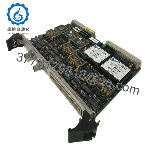
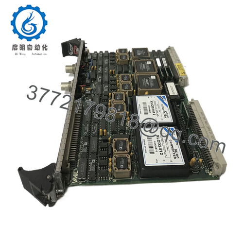
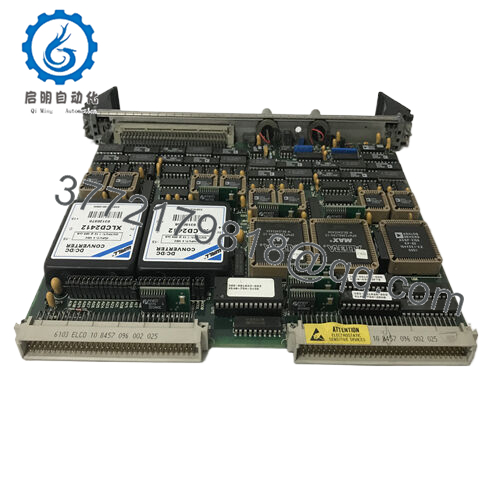
The GE VMIVME-2128 is a 128-channel digital I/O module designed for VMEbus-based control systems. It interfaces discrete field signals with high channel density, commonly deployed in test systems, aerospace simulation rigs, and legacy industrial automation platforms requiring deterministic I/O handling.
This product is a Brand New Surplus unit. It is not used, not pulled from a decommissioned plant, and not refurbished. For aging VME infrastructures, securing New Surplus inventory is a direct hedge against obsolescence write-offs and extended lead time variability. Compared to uncertain secondary-market parts, this approach stabilizes Total Cost of Ownership (TCO) and prevents stock-out incidents in mission-critical systems.

- VMIVME-2128
5. Installation & Configuration Guide
Stage 1: Pre-Installation (Prep & Safety)
- Apply lock-out/tag-out to the VME rack.
- Use an ESD wrist strap and grounded work surface.
- Photograph existing module: slot position, ribbon cable orientation, and any configuration jumpers.
Stage 2: Removal
- Power down the chassis fully.
- Disconnect front-panel cables carefully to avoid pin damage.
- Release ejector handles evenly and extract the module without twisting.
Stage 3: Installation (Clone & Seat)
- Replicate any jumper or configuration settings from the original board.
- Insert the VMIVME-2128 into the correct VME slot; engage ejector handles firmly.
- Reconnect cables, verifying correct pin alignment.
Stage 4: Power-On & Testing
- Restore power and monitor system voltage rails.
- Check system diagnostics for board recognition.
- Validate I/O states via test signals and confirm interrupt functionality.
6. Firmware/Software Versions & Upgrade Notes
- Firmware Dependency: Typically minimal onboard firmware; functionality relies on host VME controller and driver stack.
- Compatibility Note: Ensure existing VME CPU firmware and drivers support the VMIVME-2128 addressing scheme.
- Driver Alignment: Legacy systems may require specific driver revisions—document before replacement.
- Upgrade Risk: Avoid modifying system firmware during hardware swap; changes can disrupt I/O mapping and interrupt handling.
7. Frequently Asked Questions (FAQ)
Q1: Are these units genuinely new?
Yes. These are New Surplus modules with zero field usage. Original PCB condition, no solder rework, and full QC validation included.
Q2: Why not use refurbished I/O cards?
Discrete I/O modules degrade over time—especially output drivers. A failure can propagate incorrect signals into the control system. The cost of a single misfire often exceeds the savings from buying lower-cost alternatives.
Q3: Is this module obsolete?
The VMIVME-2128 is part of a legacy VME ecosystem. OEM production is limited. A last-time-buy strategy is strongly recommended to avoid future stock-outs.
Q4: Can I hot-swap this module in a VME rack?
No. Standard VME systems are not hot-swappable unless specifically engineered. Always power down before replacement.
Q5: Does the module require configuration after installation?
Yes. Addressing and I/O direction may require software configuration. Always mirror the previous setup to avoid system faults.
Q6: What stocking strategy do you recommend?
Maintain minimum 1–2 units as buffer stock per critical rack. For multi-site operations, implement cross-site sharing and vendor consolidation to reduce carrying cost while ensuring availability.
Q7: What warranty and verification are provided?
Each unit includes a 12month warranty, serial traceability, and full QC test documentation including functional and electrical verification.


