
 WhatsApp: +86 16626708626
 Email:
  Phone: +86 16626708626
Description
3. Key Technical Specifications
| Parameter | Value |
|---|---|
| I/O Capacity | 128-bit TTL digital I/O |
| Port Structure | 16 ports × 8 bits |
| Signal Type | TTL compatible (positive/negative logic options) |
| Output Current | Up to 24 mA sink per channel |
| Data Transfer | 8-bit or 16-bit transfers |
| Interface | VMEbus (double Eurocard form factor) |
| Connector | 64-pin DIN 41612 |
| Addressing | Short I/O (supervisory or non-privileged) |
| Configuration | DIP switches + jumper-based port direction |
| Diagnostics | Loopback capability + configurable addressing |
| Power Consumption | Typical VME board range (~5–10 W) |
| Lifecycle Status | End-of-Life (OEM support limited) |
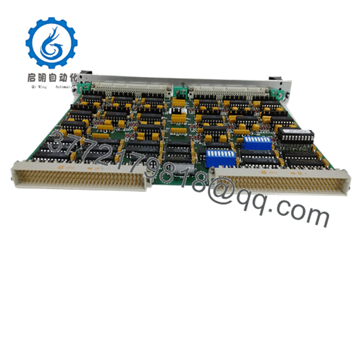
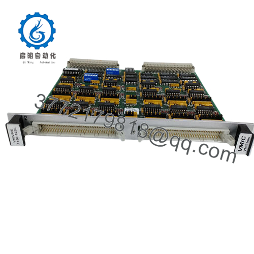
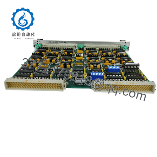
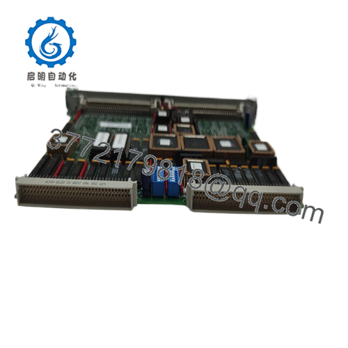
The module provides 128 TTL-compatible I/O points with configurable direction per port and supports both 8-bit and 16-bit data transfers.
4. Product Introduction & Supply Chain Strategy
The GE VMIVME-2528 is a high-density VMEbus digital I/O board designed for deterministic signal exchange in embedded control systems, aerospace test platforms, and legacy industrial automation architectures requiring TTL-level interfacing.
From a supply-chain perspective, this module is firmly in EOL status, with availability limited to surplus channels. Securing New Surplus inventory avoids hidden failure modes seen in refurbished boards (aged ICs, degraded output drivers). A structured last-time-buy combined with buffer stock planning mitigates lead time variability and protects long-term system uptime, directly improving Total Cost of Ownership (TCO).
5. Installation & Configuration Guide
Stage 1: Pre-Installation (Prep & Safety)
- Execute lock-out/tag-out procedures on the VME rack.
- Wear a grounded ESD wrist strap.
- Document DIP switch settings and jumper configurations.
- Label all connected I/O cables (64-pin interface).
Stage 2: Removal
- Power down the VME chassis completely.
- Loosen front panel screws/ejectors.
- Use ejector handles evenly—avoid PCB flexing.
Stage 3: Installation (Clone & Seat)
- Replicate all DIP switch and jumper settings (critical for address mapping).
- Align with card guides and insert evenly.
- Engage ejectors fully to seat into backplane connectors.
Stage 4: Power-On & Testing
- Restore power and monitor system status.
- Verify address mapping recognition in CPU.
- Perform loopback or I/O simulation testing.
- Confirm stable 8/16-bit data transfers without bus errors.

- VMIVME-2528
6. Firmware/Software Versions & Upgrade Notes
- No onboard firmware in the traditional sense; configuration is hardware-based (DIP switches and jumpers).
- Compatibility depends on VME controller and system software drivers.
- Address conflicts are the primary integration risk—validate I/O mapping before power-up.
- Avoid simultaneous controller firmware upgrades during board replacement to isolate fault domains.
7. Frequently Asked Questions (FAQ)
Q1: Is this unit truly new or surplus?
This product is a Brand New Surplus unit. It is not used, not pulled from a decommissioned plant, and not refurbished. It maintains original OEM integrity with zero connector wear and no rework.
Q2: Why is New Surplus preferred over refurbished boards?
Refurbished boards often contain aging TTL drivers and degraded solder joints. A failure in a 128-channel I/O board can cascade across multiple signals, leading to system-wide faults.
Q3: Is the VMIVME-2528 obsolete?
Yes. It is an EOL VME module with no active OEM production. Strategic last-time-buy and vendor consolidation are strongly recommended.
Q4: What stocking strategy do you recommend?
- Critical systems: Minimum 1–2 units as buffer stock
- High-utilization systems: Define Min/Max based on failure rate and lead time variability
- Multi-site operations: Enable cross-site spare sharing
Q5: Can this module be hot-swapped?
No. VMEbus systems typically require full power-down to avoid bus faults and hardware damage.
Q6: What are the main configuration risks?
Incorrect DIP switch settings or jumper configurations can cause address conflicts or incorrect I/O direction assignment.
Q7: What warranty is provided?
12months warranty with full QC verification, including functional testing, signal validation, and traceable serial documentation.


