
 WhatsApp: +86 16626708626
 Email:
  Phone: +86 16626708626
Description
Key Technical Specifications
| Parameter | VMIVME-2540-000 |
|---|---|
| Manufacturer | VMIC / GE Fanuc / Abaco Systems |
| Model | VMIVME-2540-000 |
| Module Type | Intelligent Counter/Controller |
| Bus Architecture | VMEbus |
| Form Factor | 6U VME |
| Channel Configuration | 4-channel option |
| Local CPU | Motorola 68HC000 |
| CPU Speed | 15 MHz |
| Timing Controller | AM9513A STC |
| Digital Signal Interface | TTL / RS-422 |
| Data Transfer | 8, 16, 24, or 32 bit |
| Maximum Event Count | Up to 4 giga-events |
| Frequency Measurement | Up to 2.5 MHz |
| Square-Wave / Pulse Generation | 0.0076 Hz to 2.5 MHz |
| Period Measurement | Down to 400 ns |
| VME Interface | VMEbus slave interface |
The original VMIC technical documentation describes the VMIVME-2540 as an Intelligent Counter/Controller (ICC) containing three principal sections: the VMEbus slave interface, an onboard CPU with firmware/support logic, and the measurement/control circuitry.
The current Abaco product documentation lists the VME-2540 with 24-channel I/O, while the original ordering table shows that the hardware was available in 4-, 8-, 16-, and 24-channel interface configurations. Therefore, the complete ordering code is important when determining the exact installed configuration.
Product Introduction
The VMIVME-2540-000 is a legacy VMEbus intelligent counter/controller designed for applications requiring deterministic digital timing, event counting, frequency measurement, pulse measurement, and programmable signal generation. Its onboard 68HC000 processor handles configuration and control of the timing circuitry, reducing the amount of direct low-level programming required by the host VME processor.
The module can perform functions including event counting, frequency measurement, period and pulse-width measurement, square-wave generation, pulse-train generation, division, timers, periodic interrupts, and quadrature position measurement. These capabilities make it useful in legacy test systems, motion-related equipment, instrumentation, and industrial control platforms where a VME architecture is still in service.
A key engineering point is that this board is a programmable digital measurement/controller, not a conventional analog acquisition module. If an existing system expects analog voltage or current inputs, VMIVME-2540-000 is not a direct functional substitute.
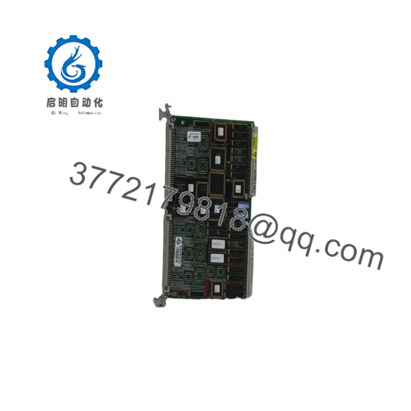
VMIVME-2540-000
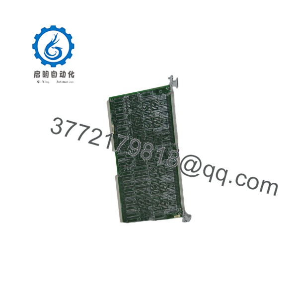
VMIVME-2540-000
Installation & Configuration Guide
Stage 1 — Pre-Installation Preparation | ~5 minutes
- Identify the complete board number, including the
-000suffix. - Record the VME chassis slot occupied by the original module.
- Back up the host application’s VME configuration and board initialization data.
- Photograph the front-panel connectors and switch/jumper settings.
- Identify the connected signal type: TTL, RS-422, or the appropriate configured interface.
- Confirm the channel count required by the application.
- Verify the VME chassis power and cooling conditions.
⚠️ Do not assume every VMIVME-2540 has the same channel/interface configuration. The original ordering information specifies multiple interface options.
Stage 2 — Remove the Existing Module | ~5 minutes
- Shut down the host system according to the equipment manufacturer’s procedure.
- Remove power from the VME chassis unless the system specifically supports controlled live replacement.
- Label all front-panel signal cables.
- Disconnect the cables without pulling on the conductors.
- Release the VME card ejectors.
- Pull the module straight out of the card guides.
- Inspect the VME P1/P2 connectors for contamination or bent contacts.
⚠️ Do not treat the as a generic hot-swappable VME I/O card. Follow the chassis and system manufacturer’s replacement procedure.
Stage 3 — Install the Replacement | ~5 minutes
- Verify that the replacement is or an explicitly approved equivalent.
- Inspect the PCB and VME connectors.
- Check switches, jumpers, and interface configuration against the original board.
- Align the board with the VME card guides.
- Insert it evenly into the backplane connectors.
- Secure the card ejectors and front-panel retaining hardware.
- Reconnect each signal cable to its documented position.
- Verify that cables do not interfere with adjacent VME boards.
The uses an onboard processor and firmware to provide a command-driven interface to its measurement and generation functions. Consequently, replacing the hardware without restoring the application’s board initialization can leave the module physically installed but functionally misconfigured.
Stage 4 — Power-On & Functional Testing | ~10–20 minutes
- Restore VME chassis power.
- Confirm normal system initialization.
- Verify that the host recognizes the board at the expected VME address.
- Confirm the configured channel count.
- Test event counting with a known pulse source.
- Test frequency measurement against a calibrated or known-frequency source.
- Verify pulse-width or period measurements where used.
- Test programmed outputs without connecting them to critical equipment initially.
- Confirm any quadrature or position signals if applicable.
- Record the final VME address, configuration, firmware status, and test results.
For frequency applications, the published VME-2540 specification reaches 2.5 MHz, while pulse/square-wave generation is specified from approximately 0.0076 Hz to 2.5 MHz.
Frequently Asked Questions (FAQ)
What is the -000?
It is a VMEbus Intelligent Counter/Controller from the VMIC product family, later associated with GE Fanuc and Abaco Systems. The board provides programmable digital measurement and signal-generation functions.
What processor does the use?
The module incorporates a Motorola 68HC000 processor operating at 15 MHz. The local processor manages the onboard timing and counter functions through firmware.
What can the measure?
Depending on configuration, it can perform event counting, frequency measurement, period measurement, pulse-width measurement, and quadrature position measurement.
Can the generate signals?
Yes. Its functions include programmable square-wave and pulse-train generation, timers, periodic interrupts, and frequency division. The published generation range extends to 2.5 MHz.
Is -000 a 24-channel board?
This requires care. The family supports multiple channel/interface configurations. The original ordering table identifies 4, 8, 16, and 24-channel options, while current Abaco documentation describes the VME-2540 family as a 24-channel module. Therefore, the complete part number and board markings should be checked before assuming channel capacity.
Is the -000 obsolete?
It is a legacy VME product. Abaco currently maintains product documentation for the VME-2540 family, while secondary-market listings id as an EOL/legacy item.
Can another VME counter card replace it?
Not automatically. A replacement must match the VME interface, channel configuration, signal levels, register/command interface, timing behavior, host software, and application firmware assumptions. A physically compatible 6U VME card can still be functionally incompatible.
What should be included in an RFQ?
Specify:
- Complete board revision/serial information
- Channel/interface configuration
- Required signal type
- VME chassis and slot information
- Existing firmware/application compatibility requirements
- Required condition: new surplus, refurbished, or tested used
- Quantity
- Warranty and functional-test requirements
For a legacy VME system, I would request front-panel and PCB photographs before accepting a claimed equivalent. The channel/interface option is one of the first things to verify.



