
 WhatsApp: +86 16626708626
 Email:
 Phone: +86 16626708626
Description
Core Product Summary
The GE VMIVME-3122 is a high-performance 16-bit analog-to-digital converter (ADC) board for VMEbus data-acquisition systems. It scans and digitizes up to 64 differential or single-ended analog input channels and stores the converted values in a dual-port data buffer accessible from the VMEbus.
The board provides software-selectable scanning from 381 Hz to 100 kHz in the high-performance option, or up to 50 kHz in the standard-performance option. It supports programmable x1 or x10 gain, jumper-selectable input ranges from ±2.5 V to ±10 V, software and external triggering, interval-timed acquisition, optional low-pass input filters, and synchronization of up to 16 boards.
Key Technical Specifications
| Parameter | GE VMIVME-3122 |
|---|---|
| Manufacturer | VMIC / GE Fanuc |
| Product type | 16-bit analog-to-digital converter (ADC) board |
| System family | VMIC VMEbus analog input/output products |
| Form factor | 6U, 4 HP single-slot VME Eurocard |
| Input channels | 16, 32, or 64 differential or single-ended inputs, depending on ordering option |
| ADC resolution | 16 bits |
| Conversion rate, high-performance option | 381 Hz to 100 kSPS |
| Conversion rate, standard-performance option | 381 Hz to 50 kSPS |
| Scan block size | 1, 8, 16, 32, or 64 channels |
| Data buffer | 16 to 1,024 contiguous 16-bit words, dual-port |
| A/D converter ranges | ±2.5 V, ±5 V, ±10 V, 0 to +5 V, 0 to +10 V |
| Programmable gain | x1 or x10, fixed or per channel |
| Full-scale input range at gain x1 | ±1 V to ±10 V bipolar; 0 to +5 V or 0 to +10 V unipolar |
| Full-scale input range at gain x10 | ±250 mV to ±1 V bipolar; 0 to +0.5 V unipolar |
| Input impedance | 5 MΩ minimum in parallel with 50 pF |
| Input bias current | 40 nA maximum at zero input |
| Overvoltage protection | ±35 V sustained with power on/off; ±80 V transient for up to 1 second |
| Trigger modes | Software, external, interval timer |
| Scan modes | Autoscan, single scan, random access |
| VMEbus access | A16, A24, or A32; D8 or D16 data transfers |
| VMEbus compliance | ANSI/IEEE STD 1014-1987, IEC 821 and 297 |
| Interrupts | Programmable VMEbus interrupter, IRQ1–IRQ7, ROAK |
| Interval timer range | 305 µs to 687 seconds |
| Optional input filters | Low-pass filters at 10, 50, 100, or 500 Hz, -3 dB |
| Dimensions | 9.2 in × 6.3 in × 0.8 in (233.4 mm × 160 mm × 20.3 mm) |
| Weight | 700 g maximum |
| Power requirement | +5 VDC, 7.0 A maximum |
| Operating temperature | 0 to +65°C |
| Storage temperature | -40 to +85°C |
| Operating altitude | 0 to 10,000 ft (3,000 m) |
| Relative humidity | 0% to 80%, noncondensing |
| Cooling | Forced-air cooling required |
Engineering Selection Highlights
- The VMIVME-3122 is a VMEbus analog-input board, not a general-purpose controller; it requires a VME processor or host controller to configure scanning, read data, and manage interrupts.
- Its 16-bit ADC resolution and selectable x1/x10 gain make channel scaling a key selection factor: gain x10 reduces the usable full-scale input range by a factor of ten.
- The ordering suffix determines channel count, performance class, input wiring style, connector type, filter option, and conformal coating; the base model designation alone does not establish those exact options.
- High-performance versions support scanning rates up to 100 kSPS, while standard-performance versions must be programmed to 50 kSPS or less after reset for accurate conversion.
- The 1,024-word dual-port buffer allows the VME host to read data while the board continues acquiring channels.
- External triggering through the P2 connector can synchronize up to 16 VMIVME-3122 boards for simultaneous scanning.
- The board is designed to connect directly to VMIC signal-conditioning boards for thermocouple, RTD, and strain-gauge signals; direct field-wiring suitability depends on the selected input range and signal level.
System Compatibility & Integration Requirements
| Item / Dependency | Verified Compatibility or Requirement | Practical Note |
|---|---|---|
| System platform | VMEbus | The board is a 6U VMEbus slave module. |
| VMEbus compliance | ANSI/IEEE STD 1014-1987, IEC 821 and 297 | Supports A32/A24/A16:D16/D8 (EO) DTB slave operation. |
| Address space | A16, A24, or A32 | Address mode and access privilege are jumper selectable. |
| Data transfers | D8 and D16 | The VME host accesses control registers and data-buffer memory using these transfer widths. |
| Analog inputs | Differential or single-ended, depending on ordering option | Input configuration is fixed by the ordered hardware option. |
| Input connectors | P3 and P4 | Channels 00–31 connect through P4; channels 32–63 connect through P3. |
| Connector options | 96-pin nonlatching or 64-pin latching DIN connectors | The 96-pin version provides a center-row ground; the 64-pin latching version does not. |
| External synchronization | P2 external trigger input and P2 trigger output | A trigger can synchronize up to 15 additional boards. |
| Signal conditioning | VMIVME-3417A, VMIVME-3418, and VMIVME-3419 conditioning boards | These boards provide isolated conditioning for selected thermocouple, RTD, strain-gauge, and low-level input applications. |
| Power | +5 VDC, 7.0 A maximum | The board generates regulated ±15 VDC internally through a DC-to-DC converter. |
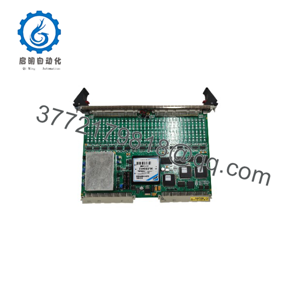
VMIVME-3122
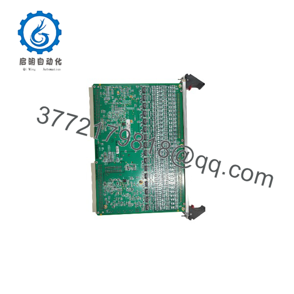
VMIVME-3122
Dimensions, Mounting & Connection Notes
- The VMIVME-3122 is a 6U, 4 HP single-slot VME Eurocard.
- Its dimensions are 9.2 inches high, 6.3 inches deep, and 0.8 inch thick (233.4 mm × 160 mm × 20.3 mm).
- The maximum board weight is 700 g.
- The board installs in a VME card cage and interfaces through VME P1 and P2 connectors.
- Analog inputs are provided through rear-panel P3 and P4 connectors.
- Channels 00 through 31 are routed through P4, while channels 32 through 63 are routed through P3.
- The input connector type depends on the ordering option: a 96-pin nonlatching DIN connector or a 64-pin latching DIN connector.
- The board requires forced-air cooling.
- The VME chassis and system cabinet must be properly grounded; the manufacturer’s safety guidance also prohibits operation in explosive atmospheres and unauthorized modification.
Detailed Product Overview
The GE VMIVME-3122 is a high-resolution analog scanning and digitizing input board for VMEbus systems. It combines input buffering, optional low-pass filtering, analog multiplexing, programmable gain, a 16-bit ADC, scan timing, dual-port data memory, interval timing, and a programmable VMEbus interrupter on a single 6U board.
The board supports 16, 32, or 64 input channels, configured as either differential or single-ended inputs according to the ordering option. Analog inputs are sampled sequentially beginning at channel 00. The digitized values are written into a dual-port data buffer, which can be read from the VMEbus at any time, including while acquisition is in progress.
The ADC provides 16-bit resolution and supports jumper-selectable full-scale converter ranges of ±2.5 V, ±5 V, ±10 V, 0 to +5 V, and 0 to +10 V. A programmable gain amplifier provides x1 or x10 gain. Gain can be fixed for all channels or assigned individually through the gain buffer, allowing mixed-amplitude signals to be acquired within one scanning sequence.
Scanning is configurable for 1, 8, 16, 32, or 64 channels. The board supports autoscan, single-scan, and random-access modes. Acquisition can run continuously, be initiated by software, be triggered externally through P2, or be timed by the onboard interval timer. The interval timer supports timed intervals from 305 µs to 687 seconds, and a burst may contain from 8 to 1,024 channel samples.
The high-performance option supports conversion rates from 381 Hz to 100 kSPS. Standard-performance options support rates up to 50 kSPS for accurate conversion; although they may sample at 100 kSPS, the manufacturer specifies that they may not convert accurately above 50 kSPS. After reset, the board enters autoscan mode with unity gain and a 100 kHz conversion rate; standard-performance configurations must be reprogrammed to 50 kSPS or less.
The dual-port buffer is programmable from 16 to 1,024 contiguous 16-bit words. Midscan and endscan flags indicate when the buffer is half filled or completely filled, and the board can generate a VMEbus interrupt at those points or after a programmed number of samples. This allows the host processor to service data without continuously polling the board.
Multiple VMIVME-3122 boards can be synchronized through the P2 external-trigger interface. A software or external trigger produces a P2 trigger output that can synchronize up to 15 additional boards, enabling coordinated acquisition across a larger VME system.
The board requires forced-air cooling and draws up to 7.0 A from the +5 VDC VME supply. It generates regulated ±15 VDC internally for its analog circuitry. Input protection is specified at ±35 V sustained and ±80 V transient for up to one second, but input configuration, grounding, and common-mode voltage still need to be designed within the documented operating limits.
Applications & System Role
The VMIVME-3122 serves as the analog-input acquisition stage in a VMEbus control or measurement system. It multiplexes selected analog channels, applies the configured gain, converts each signal to a 16-bit digital value, and stores the result in a dual-port buffer for retrieval by the VME host.
The board supports factory automation, process control, data acquisition systems, training simulators, machine monitoring, and laboratory instrumentation applications documented by VMIC. Its direct compatibility with VMIC signal-conditioning boards makes it suitable for systems where thermocouple, RTD, strain-gauge, or low-level analog signals require conditioning before digitization.
For direct analog inputs, the selected converter range and gain determine the usable signal span. For low-level or isolated field signals, the VMIVME-3417A, VMIVME-3418, or VMIVME-3419 signal-conditioning boards provide the appropriate input conditioning and isolation ahead of the VMIVME-3122.
FAQ
What is the GE VMIVME-3122?
It is a 6U VMEbus, 16-bit analog-to-digital converter board that scans and digitizes up to 64 differential or single-ended analog input channels.
How many input channels does it support?
It supports 16, 32, or 64 channels, depending on the ordering option.
What is its maximum conversion rate?
The high-performance option supports up to 100 kSPS. The standard-performance option supports accurate conversion up to 50 kSPS.
What input ranges does it support?
It supports ±2.5 V, ±5 V, ±10 V, 0 to +5 V, and 0 to +10 V A/D converter ranges, selected by jumper.
What gain settings are available?
The programmable gain amplifier provides x1 and x10 gain, either as a common setting or individually per channel.
How much onboard data buffering does it provide?
It provides a dual-port data buffer of 16 to 1,024 contiguous 16-bit words.
Can multiple boards be synchronized?
Yes. An external trigger through the P2 connector can synchronize up to 16 VMIVME-3122 boards.
What power does it require?
It requires up to 7.0 A at +5 VDC and requires forced-air cooling.



