
 WhatsApp: +86 16626708626
 Email:
  Phone: +86 16626708626
Description
3. Key Technical Specifications
| Parameter | Value |
|---|---|
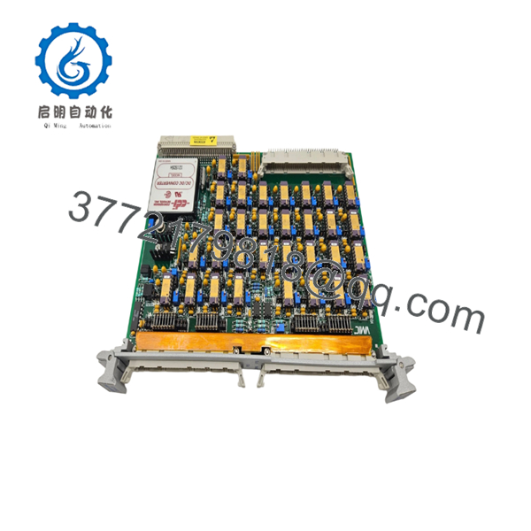
| Model Number | VMIVME-3413-000 |
| Manufacturer | GE Fanuc / VMIC |
| Product Type | Signal Conditioning Board |
| Bus Platform | VMEbus |
| Input Channels | 32 Differential or Single-Ended Analog Channels |
| Input Signal Type | Low-Level Analog Inputs |
| Supported Sensors | Thermocouples, RTDs, Strain Gauges, Pressure Transducers |
| Isolation Rating | 500 VDC Isolation from VMEbus |
| Gain Options | x1, x10, x100, x1,000 (configuration dependent) |
| Filter Options | 10 Hz, 100 Hz, 1 kHz Low-Pass Filters (variant dependent) |
| Full-Scale Input Range | 5 mV to 10 V |
| RTD Excitation | 0.1 to 10 mA per Channel |
| Strain Gauge Excitation | 2.5 V, 5 V, or 10 V at 150 mA |
| Thermocouple Support | Types E, J, K, N, B, T, R, S |
| Current Loop Support | Optional Analog Current Loop Inputs |
| Output Type | Buffered High-Level Analog Outputs |
| Companion Modules | VMIVME-3128 and other VMIC Scanning A/D Boards |
| Product Status | Discontinued by OEM |
The VMIVME-3413 was designed as a 32-channel signal conditioning platform for low-level analog signals. It interfaces directly with thermocouples, RTDs, strain gauges, pressure transducers, and other instrumentation signals while providing isolation and conditioning before analog-to-digital conversion.
4. Product Introduction
The GE VMIC VMIVME-3413-000 is a 32-channel signal conditioning board designed for VMEbus-based data acquisition and industrial measurement systems. It accepts low-level differential or single-ended analog signals from field instrumentation and converts them into conditioned high-level outputs suitable for companion VME analog input modules.
In field deployments of VMIC and GE Fanuc VME systems, the VMIVME-3413 was commonly installed ahead of VMIVME-3128 and similar scanning A/D modules when applications required thermocouple measurement, RTD monitoring, strain-gauge acquisition, or pressure transducer interfacing. Its 500 VDC isolation and configurable gain structure helped simplify mixed-signal measurement systems.

- VMIVME-3413-000
5. Installation & Configuration Guide
Stage 1: Pre-Installation Preparation (10 Minutes)
⚠️ Safety First
- Notify operations of planned downtime.
- Verify all monitored equipment is in a safe state.
- Apply Lockout/Tagout (LOTO).
- Remove power from the VME rack.
- Wait at least 5 minutes for capacitor discharge.
Tools Required
- ESD wrist strap
- PH1 screwdriver
- Fluke 115 multimeter
- Wire labels
- Smartphone camera
- VMIC wiring documentation
Data Backup
- Export application configuration files.
- Record VME slot location.
- Document gain and filter settings.
- Photograph all jumper blocks.
- Photograph field wiring terminations.
- Record thermocouple, RTD, or strain-gauge configurations.
Stage 2: Removing the Old Module (5 Minutes)
Steps
- Remove front-panel retaining screws.
- Label all field wiring.
- Disconnect input connectors carefully.
- Release extraction levers.
- Pull the module straight out.
⚠️ Note
Keep the original board available until all field signals have been validated.
Inspection Checklist
- No bent backplane pins
- No connector damage
- No oxidation
- No loose card guides
- No contamination
Stage 3: Installing the New Module (10 Minutes)
Steps
- Wear ESD protection before handling the board.
- Verify exact model number:
- VMIVME-3413-000
- Configuration Clone (Critical)
- Replicate all jumper settings.
- Match gain selections.
- Match filter settings.
- Verify sensor excitation settings.
- Insert the board into the card guides.
- Seat fully into the VME connector.
- Tighten retaining screws.
- Reconnect field wiring.
Self-Checklist
- Model verified
- Jumpers duplicated
- Gain settings matched
- Wiring secured
- Board fully seated
Stage 4: Power-On & Testing (15 Minutes)
Pre-Power Check
- Verify rack power supplies.
- Check for wiring shorts.
- Verify earth grounding.
Power-On Steps
- Energize the VME rack.
- Verify board initialization.
- Confirm communication with companion A/D modules.
- Simulate several analog inputs.
- Verify excitation voltages.
- Validate gain settings.
- Confirm signal scaling.
- Verify measurement accuracy.
⚠️ Troubleshooting Note
- Incorrect analog values: Verify gain jumpers.
- No sensor readings: Check excitation outputs.
- Excessive noise: Verify shield grounding.
- Communication issues: Check associated A/D board configuration.
SOP Quality Transparency
1. Inbound Inspection & Traceability
Every VMIVME-3413-000 undergoes:
- OEM label verification
- Serial number recording
- Anti-counterfeit inspection
- Visual inspection for:
- Corrosion
- Rework marks
- Connector wear
- PCB discoloration
- Documentation verification when available
2. Live Functional Testing
Testing is performed on a genuine VMIC VME test platform.
Procedures include:
- Power-on verification
- Channel-by-channel signal simulation
- Gain verification
- Filter verification
- Excitation voltage verification
- Isolation testing
- Continuous operation exceeding 24 hours
- Thermal monitoring
A formal test report can be supplied upon request.
3. Electrical Parameter Testing
- 500 V Megger insulation resistance test (>10 MΩ)
- Ground continuity verification
- Excitation voltage verification
- Input channel validation
4. Firmware & Configuration Verification
Although the VMIVME-3413 is primarily hardware-configured:
- Hardware revision is documented
- Jumper settings are photographed
- Factory configuration is archived
- Option codes are recorded
5. Final QC & Packaging
- QC inspector sign-off
- Anti-static ESD packaging
- Protective foam cushioning
- Heavy-duty export carton
- QC Passed label with inspection date
Test photos and test videos are available upon request.
Technical Pitfall & Survival Guide
❗ Firmware Revision Mismatch
This board itself contains minimal firmware dependency, but the associated acquisition software may expect a specific hardware revision.
I’ve seen a maintenance team replace a conditioning board only to discover the calibration database no longer matched the channel configuration.
Avoidance:
- Record board revision before removal.
- Verify software configuration compatibility.
- Match hardware revisions whenever possible.
❗ DIP Switch / Jumper Misconfiguration
This is the most common rookie mistake, but it happens constantly.
Take a picture before you pull it. I can’t stress this enough.
Avoidance:
- Photograph every jumper block.
- Record gain selections.
- Record filter settings.
- Record sensor excitation configuration.
❗ Terminal Block / Wiring Incompatibility
Signal conditioning boards often sit between field instruments and A/D hardware.
I’ve seen technicians reconnect thermocouple wiring backwards and spend hours chasing imaginary software faults.
Avoidance:
- Label every conductor.
- Verify polarity.
- Verify thermocouple type assignments.
- Verify shield termination methods.
❗ Power Draw Specifications
Many legacy VME racks have operated continuously for decades.
A replacement module may not cause a failure directly, but marginal power supplies can expose existing weaknesses.
Avoidance:
- Verify rack loading.
- Maintain a minimum 20% power reserve.
- Confirm cooling airflow.
❗ Electrostatic Discharge (ESD)
I once watched a contractor handle a signal-conditioning board during winter maintenance without an ESD strap.
The board appeared operational but developed unstable analog readings during commissioning.
Avoidance:
- Wear a grounded wrist strap.
- Use ESD-safe work surfaces.
- Store modules in anti-static packaging.
Keep these checks in mind and you’ll save yourself 90% of typical rework time.
6. Frequently Asked Questions (FAQ)
Q1. Is the VMIVME-3413-000 an A/D converter?
No.
The VMIVME-3413-000 is a signal conditioning board. Its primary role is to prepare low-level sensor signals for acquisition by companion VME analog input modules such as the VMIVME-3128 family.
Q2. Is this model obsolete?
Yes.
The VME-3413 product family entered a restricted production phase and is considered a legacy platform. Most available inventory today comes from surplus stock, strategic spare inventories, or professionally tested units.
Q3. What sensors can connect directly to this board?
The VMIVME-3413 supports:
- Thermocouples
- RTDs
- Strain gauges
- Pressure transducers
- Analog voltage signals
- Optional current-loop inputs
These capabilities made it popular in process monitoring and test systems.
Q4. Will I lose application logic when replacing the board?
No.
Application logic resides in the host processor or controller. However, calibration parameters, gain settings, filter selections, and sensor configuration data should always be documented before removal.
Q5. What is the most common startup problem after replacement?
Incorrect jumper settings.
In my experience, gain and filter configuration errors cause more startup issues than defective hardware. Always photograph the original configuration before removal.
Q6. Can I replace a VMIVME-3413-000 with a VMIVME-3413-100, -110, or -111?
Possibly, but not automatically.
The suffix identifies factory-installed options such as gain configuration, filter selections, and connector styles. Always verify the complete part number and installed option set before ordering.
Q7. What condition is typically available?
Current market inventory generally falls into these categories:
- New Original (New Surplus)
- Factory-Sealed Surplus
- Refurbished (Tested)
- Removed Working Spare


